Card edge connector and method for manufacturing same

Active Publication Date: 2017-08-24
AUTONETWORKS TECH LTD +2
View PDF0 Cites 1 Cited by
  • Summary
  • Abstract
  • Description
  • Claims
  • Application Information

AI Technical Summary

Benefits of technology

The invention relates to a card edge connector and a method of manufacturing it. The technical effects of the invention include: the guide member is securely held without being detached from the circuit board, the guide slope is formed without scraping the resilient contact portion, and the guide member is embedded within the board holding member, increasing the holding force of the guide member. These benefits contribute to the reliability and low detachment of the card edge connector.

Problems solved by technology

However, providing the structure that contacts the circuit board while the resilient pieces are resiliently deformed means that corner edge parts on a leading end in an inserting direction of the circuit board butt against the resilient pieces and are strongly abraded against the resilient pieces in the process of inserting the circuit board into the board accommodation space.
Such butting and abrasion may cause improper deformation of the resilient pieces, plating peeling on contact portions of the resilient pieces, jamming of shaving from a part of the corner edge part of the circuit board between the resilient pieces and the circuit board and, eventually, a contact failure.
An event that causes a reduction of contact reliability may occur on the resilient contact portion and the circuit board if a corner edge part on a leading end in the inserting direction of the circuit board comes into contact with the resilient contact portion in the process of inserting the circuit board into the board accommodation space.
Thus, there is no possibility of reducing contact reliability.
However, since the covering portion is formed with the guiding slope, the resilient contact portion neither strongly butts against nor is abraded against the covering portion in the process of pulling out the circuit board from the board accommodation space.

Method used


Image

  • Card edge connector and method for manufacturing same
  • Card edge connector and method for manufacturing same
  • Card edge connector and method for manufacturing same

Examples


first embodiment

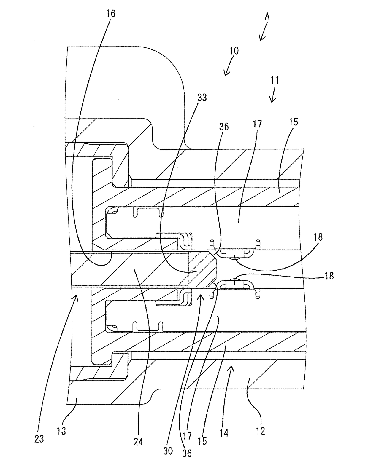
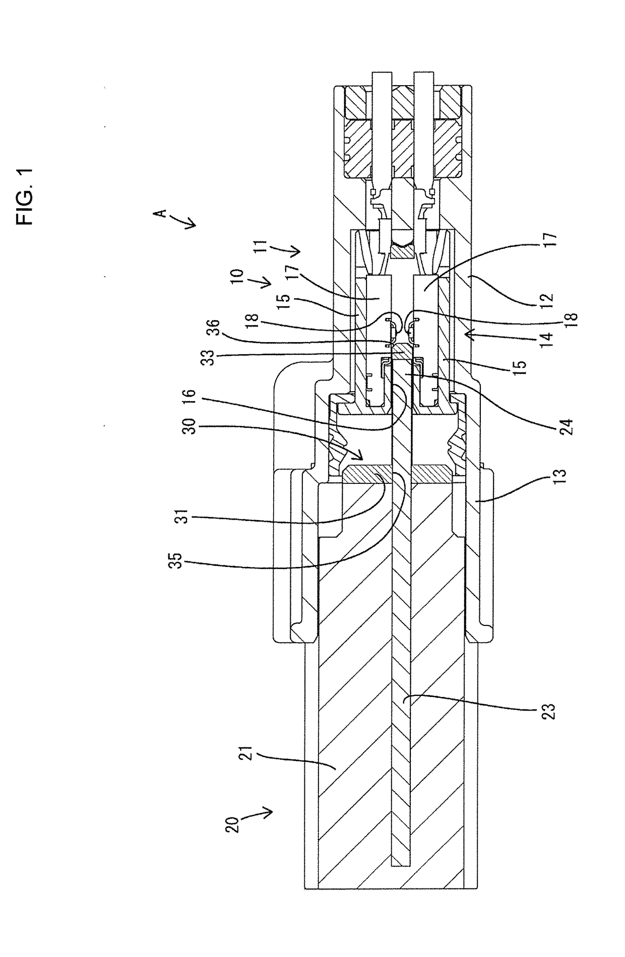
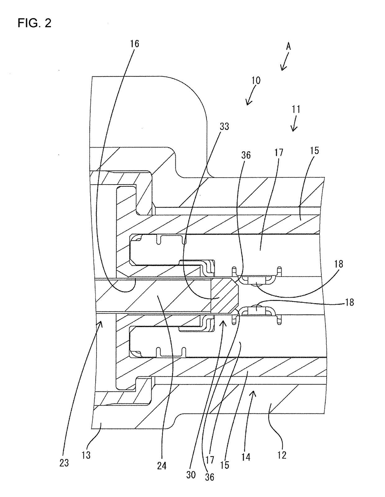
[0035]The card edge connector A of this first embodiment includes the first housing 10 formed with the board accommodation space 16 open forward, the terminal fittings 17 provided in the first housing 10 and formed with the resilient contact portions 18 projecting toward the board accommodation space 16, and the second housing 20 including the circuit board 23 to be inserted into the board accommodation space 16 from front of the first housing 10. In a state where the circuit board 23 is not inserted in the board accommodation space 16 and the resilient contact portions 18 are not resiliently deflected, a minimum interval (minimum facing distance) between the resilient contact portions 18 vertically facing each other in the board accommodation space 16 is set smaller than a plate thickness (vertical dimension) of the connecting edge portion 24. By this dimensional difference, the resilient contact portions 18 come into contact with the connecting edge portion 24 while being resilien...

second embodiment

[0043]According to the card edge connector B of this second embodiment, since a pair of upper and lower covering portions 43 sandwich the front end edge of the connecting edge portion 24 in a plate thickness direction (vertical direction), a displacement of the front frame portion 42 (guide slope 36) in the plate thickness direction with respect to the connecting edge portion 24 can be prevented. Further, the steps are formed between the front frame portion 42 and the connecting edge portion 24 by forming the covering portions 43. In view of this point, the guiding surfaces 44 are formed on the rear edge part of the covering portions 43. Since this causes resilient contact portions 18 to slide in contact with the guiding slopes 44 in the process of pulling out the circuit board 23 from the board accommodation space 16, the resilient contact portions 18 neither strongly butt against nor are abraded against the covering portions 43. Thus, plating peeling, improper deformation and the ...

third embodiment

[0044]FIGS. 8 to 10 show a card edge connector A according to the present invention.

[0045]In the first and second embodiments, the board holding member 21 is molded with the circuit board 23 inserted and, thereafter, the guide member 30 is attached. However, in this third embodiment, a guide member 30 is attached to a circuit board 23 in advance and a board holding member 21 is molded with that assembly inserted. The configuration of the guide member 30 according to this third embodiment is basically the same as the guide member 30 of the first embodiment.

[0046]FIG. 8 shows an operation status in attaching the guide member 30 to a connecting edge portion of the circuit board 23. As shown in FIG. 8, the guide member 30 includes a wall-like portion 31 having a through groove 35, a pair of side frame portions 32 extending forward from both left and right end parts of the front surface of the wall-like portion 31 and a front frame portion 33 coupling extending end edges of the both side...


PUM


Abstract

It is aimed to prevent a reduction of contact reliability. A card edge connector (A) includes a first housing (10) formed with a board accommodation space (16) open forward, terminal fittings (17) provided in the first housing (10) and formed with resilient contact portions (18) projecting toward the board accommodation space (16), a second housing (20) including a circuit board (23) to be inserted into the board accommodation space (16) from front of the first housing (10), and guide slopes (36) made of synthetic resin, provided to cover a leading edge of the circuit board (23) in an inserting direction into the board accommodation space (16) and inclined with respect to the inserting direction into the board accommodation space (16).

Description

BACKGROUND[0001]1. Field of the Invention[0002]The present invention relates to a card edge connector and a method for manufacturing the same.[0003]2. Description of the Related Art[0004]Japanese Unexamined Patent Publication No. 2008-091047 discloses a card edge connector with a housing including a board accommodation space and a plurality of terminal fittings accommodated in the housing and arranged to face each other across the board accommodation space. This card edge connector comes into contact with a circuit board inserted into the board accommodation space while resilient pieces provided in the terminal fittings are resiliently deformed. A predetermined contact pressure is ensured between the terminal fittings and the circuit board by a resilient contact action of the resilient pieces. Further, dimensional tolerances of the housing, the terminal fittings and the circuit board are absorbed by resilient deformation of the resilient pieces. Thus, a structure configured to come ...

Claims


Application Information

Patent Timeline
IPC IPC(8): H01R12/70H01R13/11H01R13/50H01R12/72
CPCH01R12/7005H01R13/50H01R13/113H01R12/721
Inventor MORIYASU, MASANORITABATA, MASAAKISHINOZAKI, TETSUYA
Owner AUTONETWORKS TECH LTD
Why Eureka
Try Eureka