Method for affixing a metal tube to a metal body

Active Publication Date: 2020-03-17
ENDRESS HAUSER FLOWTEC AG
View PDF27 Cites 0 Cited by
  • Summary
  • Abstract
  • Description
  • Claims
  • Application Information

AI Technical Summary

Benefits of technology

[0007]An object of the invention is, consequently, to provide for affixing a metal tube to a metal body a method, which is suitable to affix to a metal body by means of force-based interlocking a metal tube serviceable as a measuring tube of a measuring transducer of the vibration-type and having a wall

Problems solved by technology

Moreover, neither in the case of the internal rolling nor in the case of the press method is the application of a pressurizing medium required, a pressurizing medium, in each case, to be filled into the metal tube to be processed, consequently a pressurizing medium causing increased technical effort.
A disadvantage of the above indicated methods known from the state of the art, respectively conventionally applied in the case of the manufacture of measuring transducers of the vibration-type, based on cold deformation of a metal body and/or

Method used


Image

  • Method for affixing a metal tube to a metal body
  • Method for affixing a metal tube to a metal body
  • Method for affixing a metal tube to a metal body

Examples


Example

DETAILED DISCUSSION IN CONJUNCTION WITH THE DRAWINGS

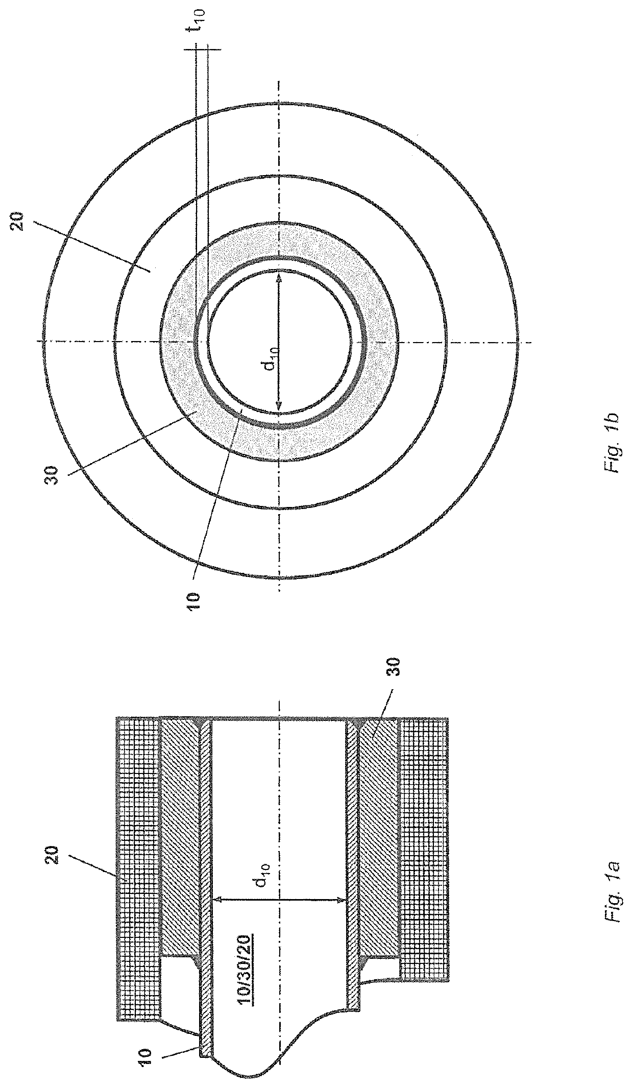
[0058]Shown schematically in FIGS. 1a and 1b are different partially sectioned views of a metal tube, metal sleeve, metal body composite system 10 / 30 / 20 formed by means of a metal tube 10, especially an at least sectionally circularly cylindrical, metal tube 10—namely a tube 10 having a lumen surrounded by a metal wall—, by means of a metal body 20, as well as by means of a metal sleeve 30—namely a sleeve having a lumen surrounded by a metal wall.

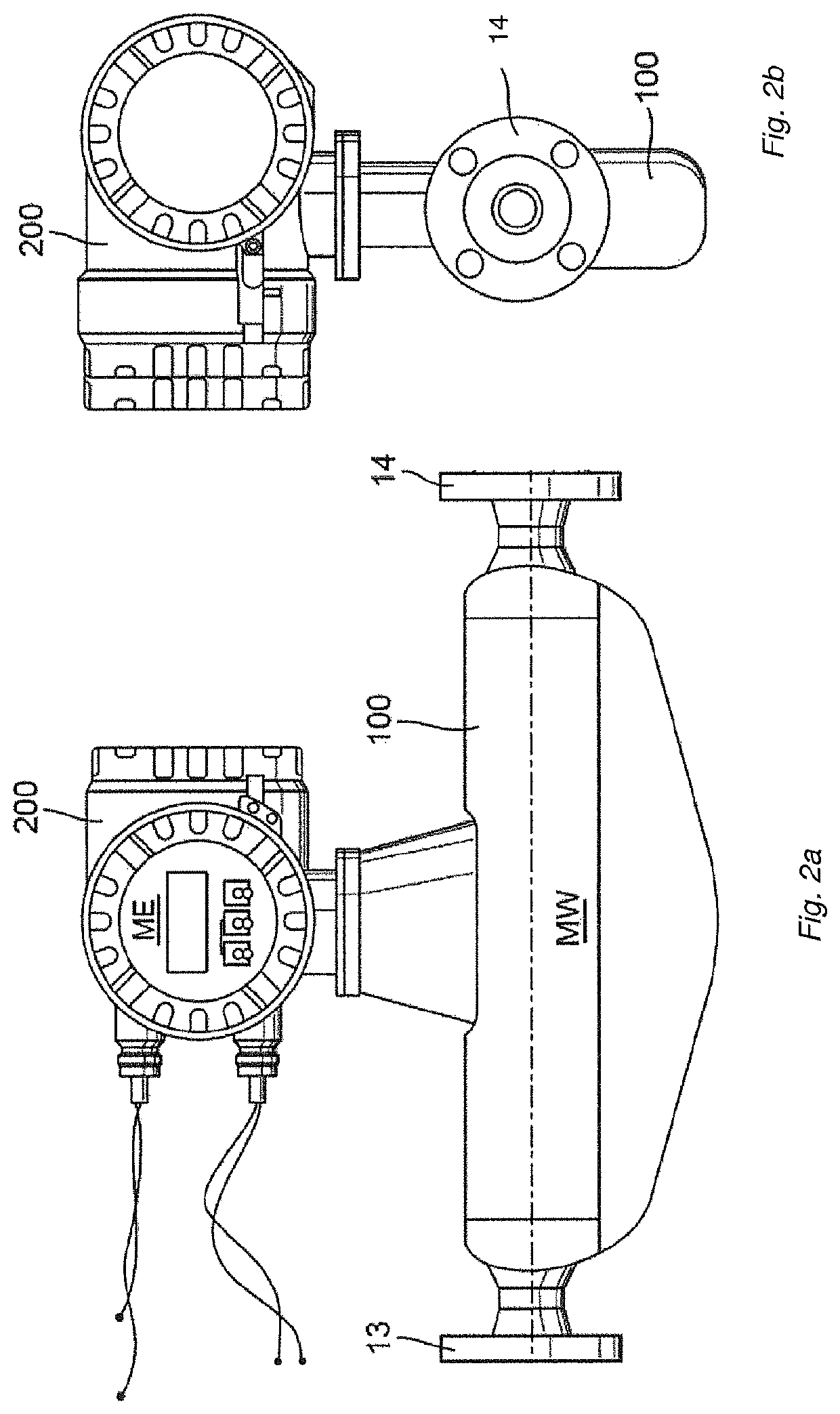
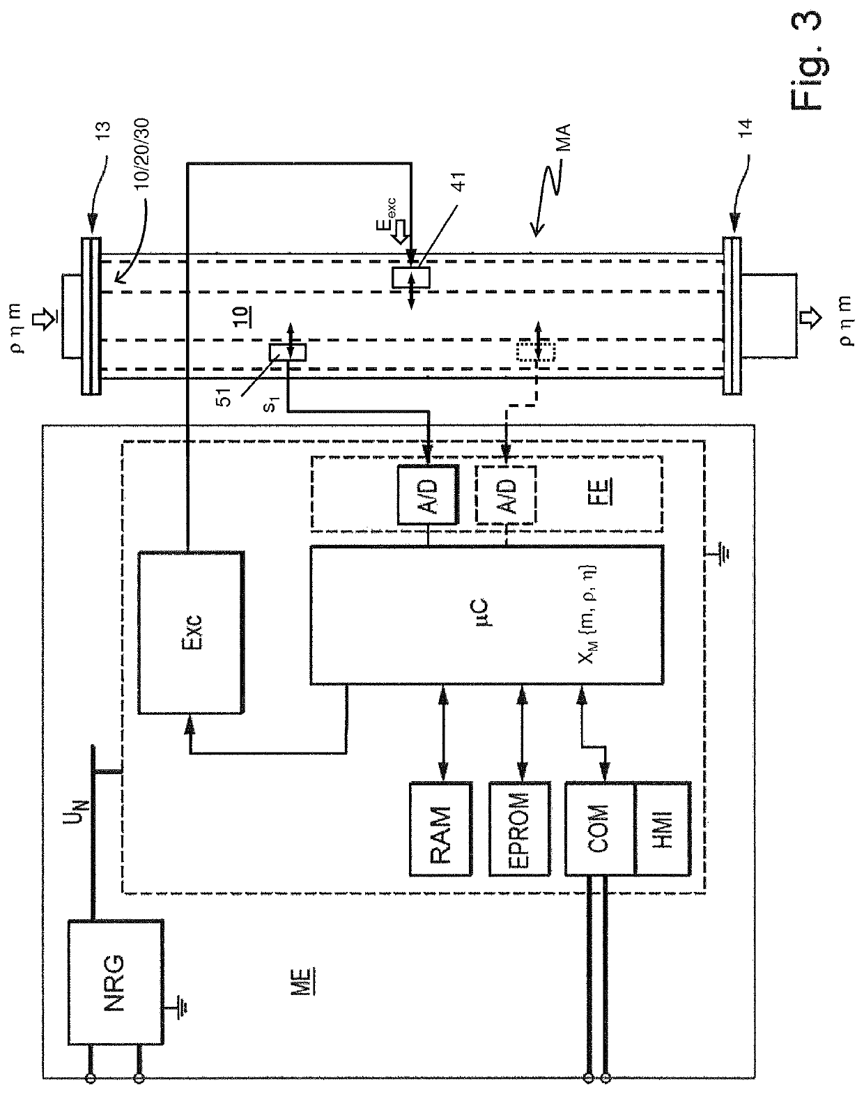
[0059]According to an embodiment of the invention, metal tube 10 is, especially, adapted to guide in its lumen a fluid, especially a fluid flowing at least at times, for example, a fluid in the form of a gas, a liquid or a flowable dispersion. The metal tube, metal sleeve, metal body composite system 10 / 30 / 20 can accordingly, such as evident from a combination of FIGS. 2a and 2b and 3, for example, also be a component of a measuring transducer MT, in the case of which composite system the ...


PUM

PropertyMeasurementUnit
Thicknessaaaaaaaaaa
Thicknessaaaaaaaaaa
Diameteraaaaaaaaaa

Abstract

In the method, a portion of the metal tube is placed in a lumen of a metal sleeve having a metal wall surrounding the lumen. The metal tube is placed in such a manner that an outer surface of the metal tube and an inner surface of the metal sleeve at least partially contact one another. The metal sleeve is affixed on the portion of the metal tube placed in its lumen for forming a metal tube, metal sleeve, composite system. The metal tube, metal sleeve, composite system, in turn, is placed in the passageway of the metal body in such a manner that an outer surface of the metal sleeve and an inner surface of the passageway at least partially contact one another, in order thereafter by plastically deforming at least the metal sleeve of the metal tube, metal sleeve, composite system placed in the passageway to form a force interlocking between the inner surface of the passageway and the outer surface of the metal sleeve. The so formed metal tube, metal sleeve, metal body composite system can serve as a component of a measuring transducer, respectively a vibronic measuring device formed therewith.

Description

TECHNICAL FIELD[0001]The invention relates to a method for affixing by means of a force interlocked connection a metal tube, especially a metal tube useful as a measuring tube of a measuring transducer of the vibration-type, to a metal body having a passageway as well as to an assembly manufactured by means of such a method, consequently an assembly comprising both a metal body as well as also a metal tube. Moreover, the invention relates to a measuring transducer comprising such an assembly, especially namely a measuring transducer of the vibration-type formed by means of such an assembly, as well as to a vibronic measuring device, especially namely a Coriolis, mass flow, measuring device, a density measuring device, respectively a viscosity measuring device, for measuring a mass flow rate, a density and / or a viscosity of a flowable medium.BACKGROUND DISCUSSION[0002]Methods useful for affixing a metal tube, namely a tube having a lumen surrounded by a metal wall, to a metal body ha...

Claims


Application Information

Patent Timeline
IPC IPC(8): B23K20/12G01F1/84B21D39/04
CPCG01F1/8404B21D39/04B23K20/12G01F1/8409
Inventor SCHUTZE, CHRISTIANBRAUN, MARCELBUTZBACH, DIRKLORENZ, RAINER
Owner ENDRESS HAUSER FLOWTEC AG
Why Eureka
Try Eureka