Steering column device

Inactive Publication Date: 2010-12-02
FUJI KIKO KK
View PDF9 Cites 29 Cited by
  • Summary
  • Abstract
  • Description
  • Claims
  • Application Information

AI Technical Summary

Benefits of technology

[0020]In the above-described configuration, a movable die or dies is or are disposed above, below, or above and below the fixed-side tooth portion to be meshable with the fixed-side tooth portion, and the urging unit is disposed between the guide member and the movable die or dies. Accordingly, the number of movable dies can be easily changed to one or two in accordance with the magnitude of an assumed impact load.
[0021]Moreover, the body mount bracket is clamped between and thus pressure-contacted wi

Problems solved by technology

The air bag cannot sufficiently reduce an impact on the driver if the air bag does not inflate in front of the driver.
In the case where a heavy load is inputted to the steering wheel, the lock pin 107

Method used


Image

  • Steering column device
  • Steering column device
  • Steering column device

Examples


Example

First Embodiment

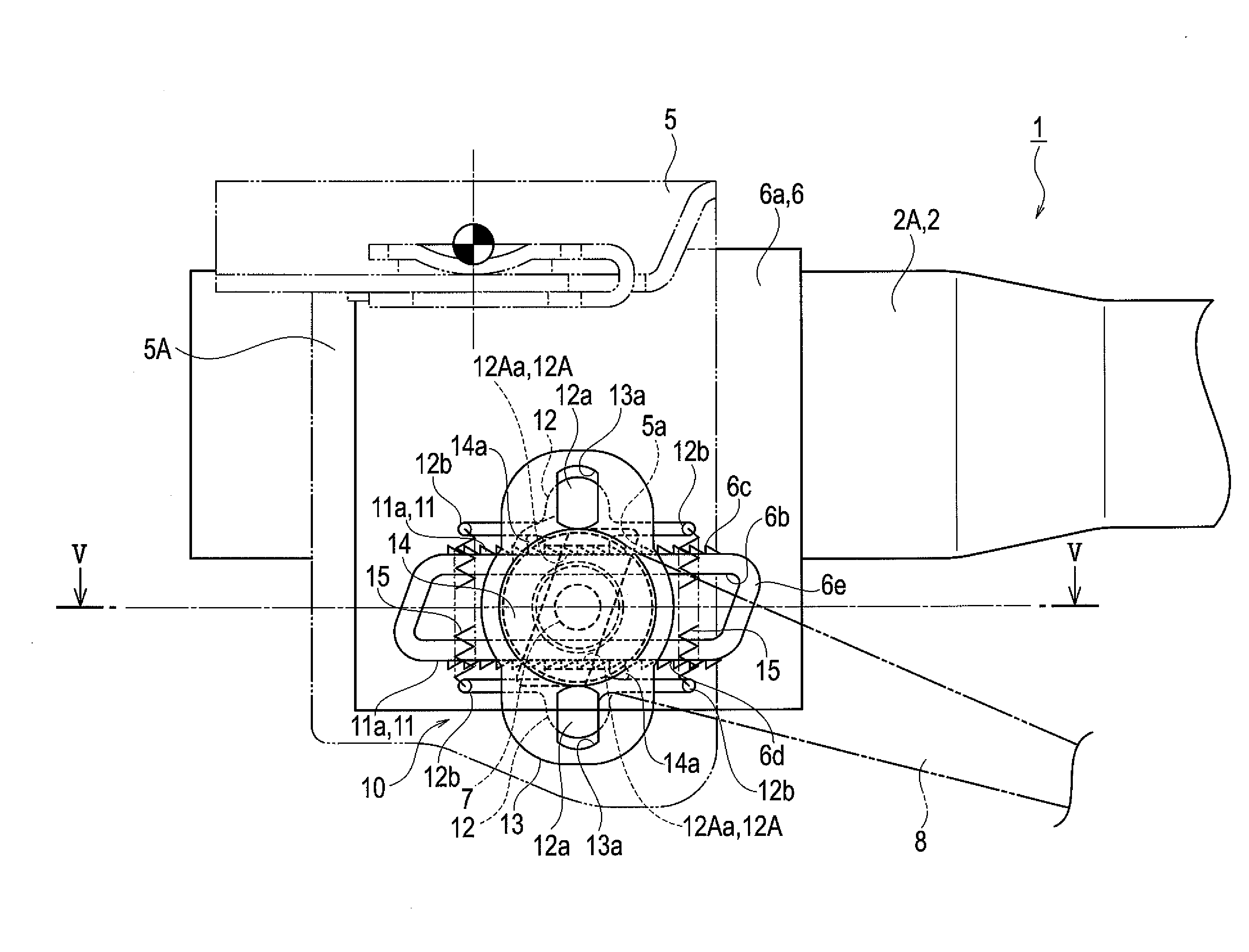
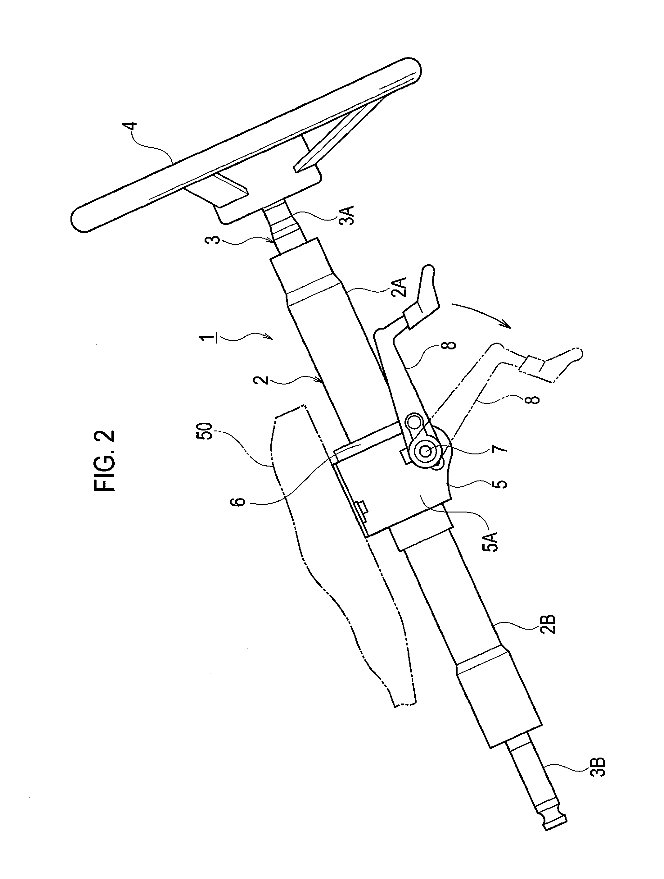
[0032]As shown in FIG. 2, a steering column device 1 according to a first embodiment of the present invention includes a cylindrical steering column tube 2 disposed to be obliquely inclined downward toward the front of a vehicle body (to the left in FIG. 2). In the steering column tube 2, a steering shaft 3 is rotatably inserted. The steering column tube 2 includes an upper tube 2A and a lower tube 2B, one of which is fitted into the other to be slidable in the axial direction. The steering shaft 3 includes an upper shaft 3A and a lower shaft 3B, one of which is spline-fitted to the other to be slidable in the axial direction. To an upper end of the upper shaft 3A, a steering wheel 4 is fixed. A lower end portion of the lower shaft 3B is connected to a steering gear box (not shown) via a universal joint (not shown).

[0033]The steering column tube 2 is clamped by a body mount bracket 5 fixed to a body bracket 50, a distance bracket 6 fixed to the steering column tube 2...

Example

Second Embodiment

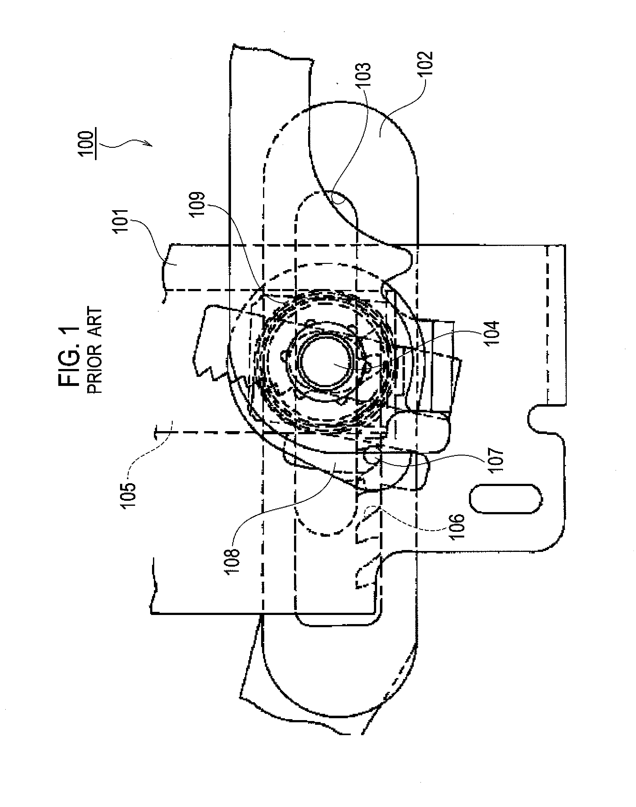
[0059]A steering column device 101 of a second embodiment of the present invention greatly differs from the steering column device 1 of the first embodiment in the configuration of a lock mechanism 20. Other components similar to those of the first embodiment are denoted by the same reference signs and will not be further described in detail.

[0060]As shown in FIGS. 6 to 8, the lock mechanism 20 of this embodiment includes a tooth plate 28 which engages with the distance bracket 6 in the direction of telescopic adjustment and which is disposed such that the sidewalls 5A of the body mount bracket 5 are interposed between the tooth plate 28 and the distance bracket 6.

[0061]The tooth plate 28 is approximately rectangular, and has an auxiliary long opening 28a formed in a central portion thereof. The auxiliary long opening 28a has a shape similar to that of the telescopic-adjustment long openings 6b provided in the distance bracket 6. At an upper edge of the tooth plate ...


PUM


Abstract

In a steering column device, when a fastening bolt is rotated to a locked side, movement of a distance bracket in a telescopic direction is restrained by a movable die displaced by an urging force of an urging unit to bring a movable-side tooth portion into mesh with a fixed-side tooth portion and by a body mount bracket and the distance bracket brought into pressure contact with each other with an axial force of the fastening bolt. When the fastening bolt is rotated to a unlocked side, a restraint of movement of the distance bracket in the telescopic direction is released by the movable die displaced by a cam protrusion to bring the movable-side tooth portion out of mesh with the fixed-side tooth portion and by the body mount bracket and the distance bracket brought out of pressure contact with each other with the axial force of the fastening bolt released.

Description

CROSS REFERENCE TO RELATED APPLICATION[0001]This application is based upon and claims the benefit of priority from the prior Japanese Patent Application No. 2009-127599, filed on May 27, 2009, the entire contents of which are incorporated herein by reference.BACKGROUND OF THE INVENTION[0002]1. Field of the Invention[0003]The present invention relates to a steering column device including a steering column tube by which a steering shaft is rotatably supported.[0004]2. Description of the Related Art[0005]A related steering column device is described in Japanese Unexamined Patent Application Publication No. Hei 8-80857. The steering column device includes a telescopic adjustment mechanism for extending or contracting a steering shaft to move a steering wheel to a position which allows a driver to comfortably drive.[0006]As shown in FIG. 1, in a steering column device 100, a nut fixed to an operation lever is screwed onto a fastening bolt 104 which passes through an upper bracket 101 to...

Claims


Application Information

Patent Timeline
IPC IPC(8): B62D1/184B62D1/18B62D1/187
CPCB62D1/184
Inventor SAKATA, TORU
Owner FUJI KIKO KK
Why Eureka
Try Eureka