

Combined spectacle lens, auxiliary lens, and method of edging lenses
- Summary
- Abstract
- Description
- Claims
- Application Information
AI Technical Summary
Benefits of technology
Problems solved by technology
Method used
Image

Examples
Embodiment Construction
[0054] An embodiment of a combined spectacle lens, an auxiliary lens, and a method of edging the combined spectacle lens of the invention will be described below. However, the invention is not limited to the embodiment shown below.
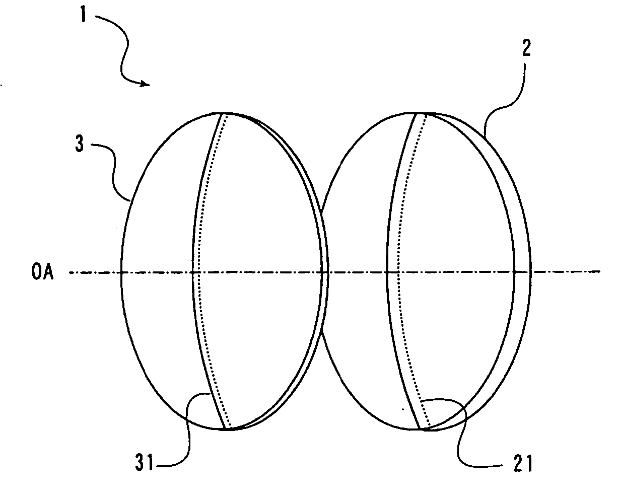
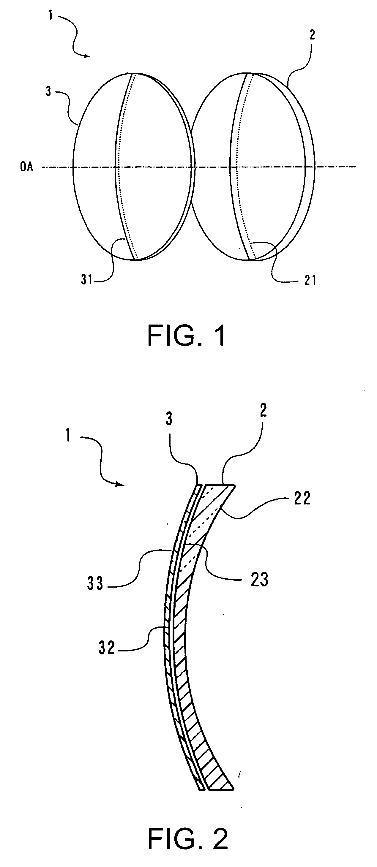
[0055] As shown in a perspective view in FIG. 1, a combined spectacle lens 1 of the invention includes a basic lens 2 which is a progressive-power lens and an auxiliary lens 3 used only for an application to be combined with the basic lens 2 and has a power to convert a design type of the basic lens 2. The basic lens 2 and the auxiliary lens 3 are used by being combined so as to align a principal meridian 21 of the basic lens 2 and a principal fixation line 31 of the auxiliary lens 3 to be aligned with the principal meridian 21, and align optical axes OA of the basic lens 2 and the auxiliary lens 3.
[0056] As shown in a cross-section of the combined spectacle lens 1 in FIG. 2, a combination mode in which the basic lens 2 is arranged on an eyeball side and...
PUM
 Abstract
Description
Claims
Application Information