
Active magnetostrictive sensor for automotive horn or occupant weight sensor

Inactive Publication Date: 2002-09-12
KEY SAFETY SYST
View PDF13 Cites 15 Cited by
  • Summary
  • Abstract
  • Description
  • Claims
  • Application Information

AI Technical Summary

Benefits of technology

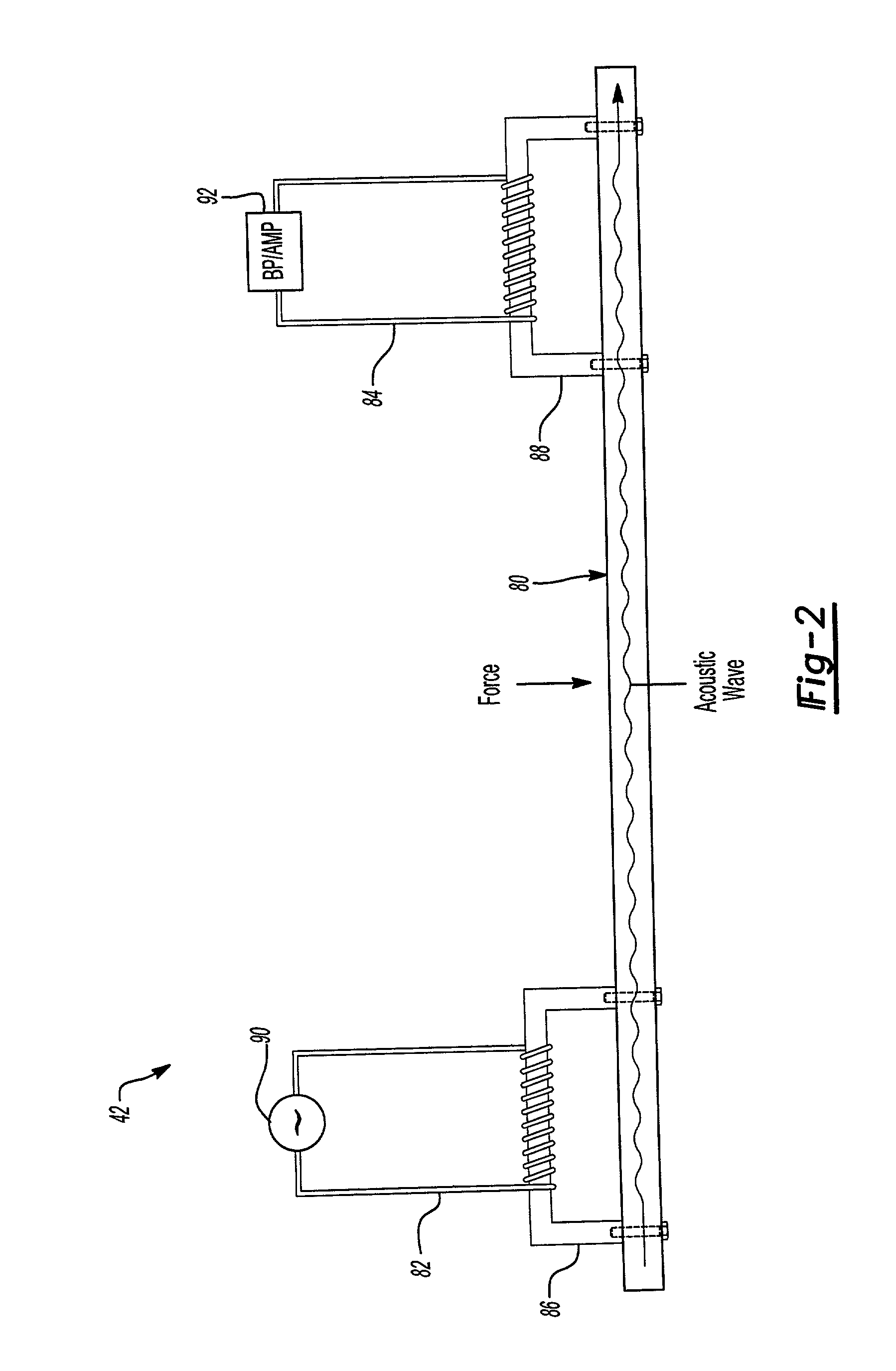
[0009] The present invention further provides a system for activating a horn. The ferromagnetic element is coupled to a contact surface, which is activated by a user desiring to activate the horn. The force exerted by the user on the contact surface is measured by analyzing the signal (voltage and / or current) received by the detection coil. If a predetermined change is detected by the associated electronics, the system activates the horn. This system provides a more constant force requirement across the area of the contact surface and under different operating conditions, such as temperature. Further, because the threshold can be adjusted in the electronics or software, the force required to activate the horn can be easily changed, such as for different vehicles or for user preference.

Problems solved by technology

Current horn sensor designs have a large variability in force over the operating area of the sensor.
Further, the sensitivity level of the sensor cannot be adjusted easily without significant time and expense for retooling.
However, this design may not always measure all of the weight on the seat, which may not be transmitted to the wires under the cushion, depending upon the position of the passenger.

Method used


Image

  • Active magnetostrictive sensor for automotive horn or occupant weight sensor
  • Active magnetostrictive sensor for automotive horn or occupant weight sensor
  • Active magnetostrictive sensor for automotive horn or occupant weight sensor

Examples


Embodiment Construction

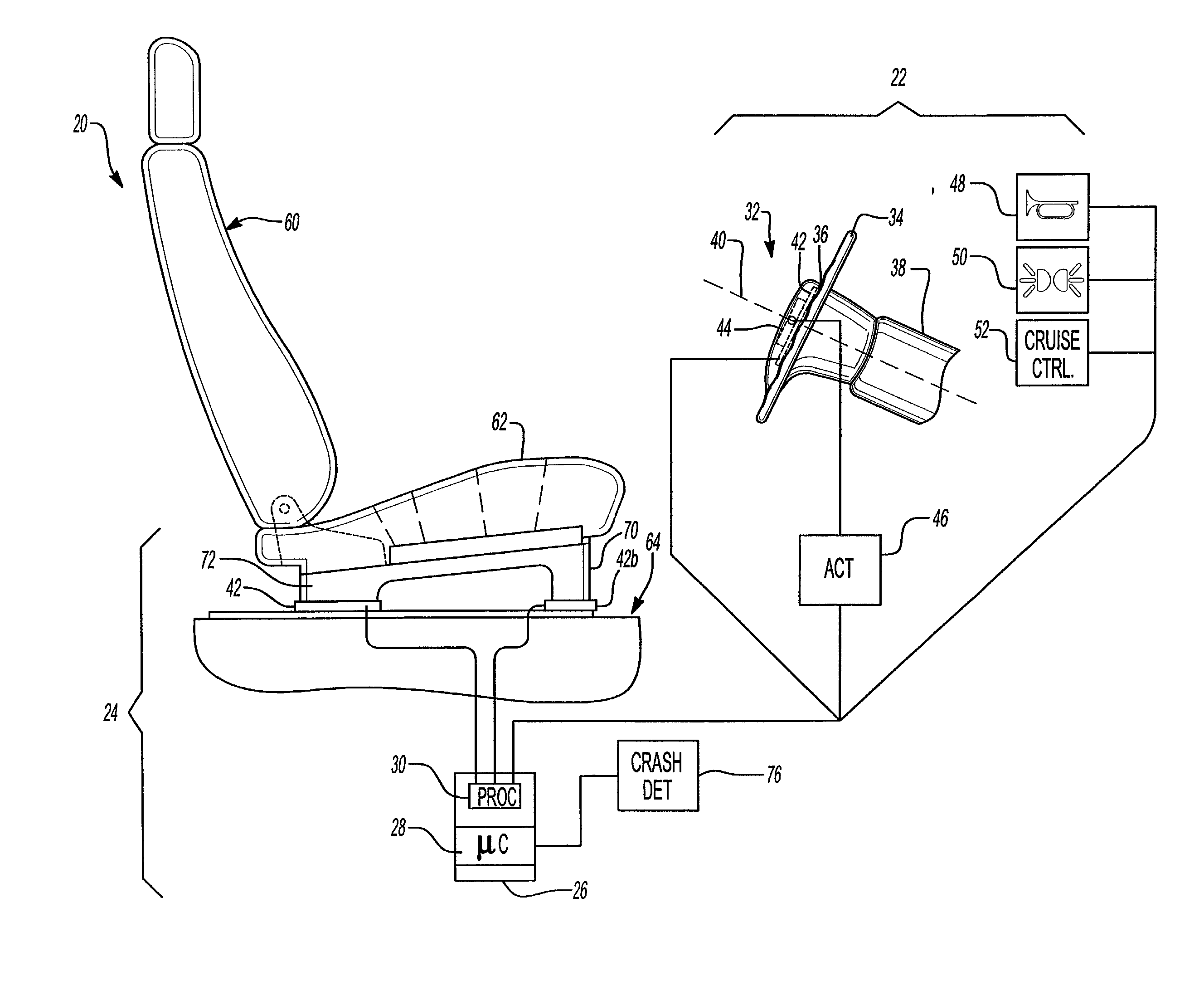
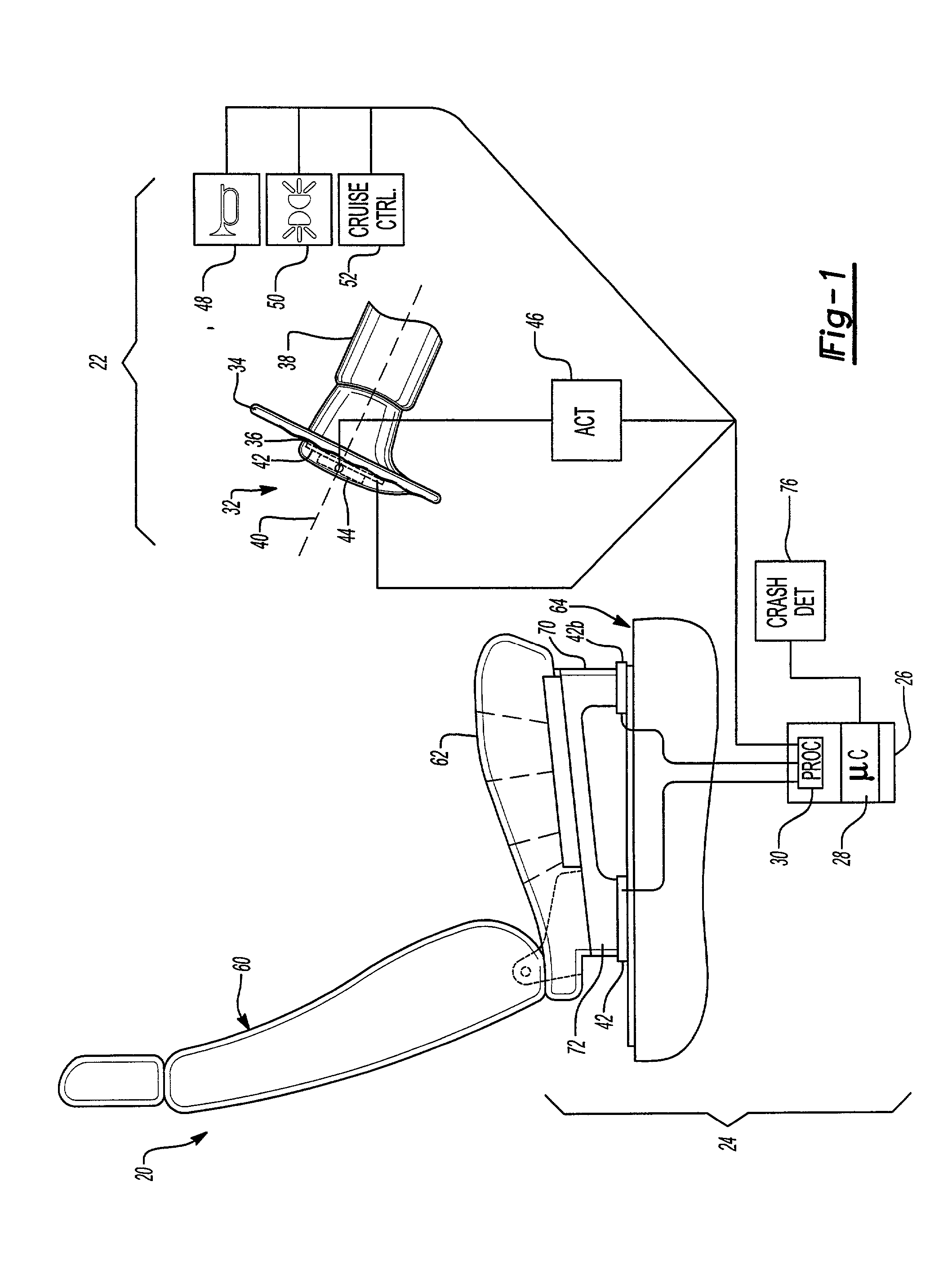
[0024] The present invention provides a force sensing system 20 implemented here as a user activated switching system 22 and occupant weight sensing system 24 both utilizing a controller 26. The controller 26 includes a microprocessor 28 (including associated memory, storage, RAM, etc.) and any necessary signal processor 30, such as amplifiers, filters, analog to digital converters, etc. It should be noted that signal processing could be provided by the microprocessor 28 in a known manner. Generally, the user activated switching system 22 activates vehicle functions when selected by a user, while occupant weight sensing system 24 determines the presence, weight and / or position of an occupant in the vehicle.

[0025] The user activated switching system 22 is illustrated as installed on a vehicle steering wheel 32 because this location benefits greatly from the present invention, although it should be recognized that the switching system 22 could also be utilized in other locations in th...


PUM


Abstract

An improved force-measurement system utilizes active magnetostrictive sensors for generating a signal representative of a force, such as the weight of a person or thing on a seat within a motor vehicle, or the force applied to the horn sensor switch on a vehicle steering wheel. The active magnetostrictive sensor includes an excitation coil and a detection coil.

Description

RELATED APPLICATIONS[0001] This application claims priority to U.S. Provisional Application No. 60 / 271,617; filed on Feb. 27, 2001.BACKGROUND OF THE INVENTION[0002] The present invention relates to an improved system and method for activation of a vehicle horn or other vehicle functions and for detecting the weight of a person seated within a motor vehicle.[0003] Current horn sensor designs have a large variability in force over the operating area of the sensor. In other words, the force needed to activate the horn may vary greatly between two different points on the horn sensor contact surface. Even at a given location on the horn sensor contact surface, the force required may also vary (e.g. two to seven pounds) over operating conditions, such as temperature, etc. Further, the sensitivity level of the sensor cannot be adjusted easily without significant time and expense for retooling.[0004] Current vehicles include an airbag for the driver as well as the front seat passenger. The ...

Claims


Application Information

Patent Timeline
IPC IPC(8): B60N2/00B60Q5/00B60R21/01B60R21/015G01L1/12
CPCB60N2/002B60Q5/003B60R21/01532B60R21/01512
Inventor GIOUTSOS, TONYJANISZEWSKI, ROBERTLABADIE, STEVE
Owner KEY SAFETY SYST
Learn More