Image forming apparatus

Active Publication Date: 2005-09-08
KK TOSHIBA +1
View PDF6 Cites 12 Cited by
  • Summary
  • Abstract
  • Description
  • Claims
  • Application Information

AI Technical Summary

Benefits of technology

[0009] It is an object of this invention to provide an image forming apparatus equipped with a hot pressure fixing device capable of making the op

Problems solved by technology

When heating and pressing to a recording medium are excessive at the time of fixing, the recording medium may shrink or wrinkle and o

Method used


Image

  • Image forming apparatus
  • Image forming apparatus
  • Image forming apparatus

Examples


Embodiment Construction

[0022] A preferred embodiment of this invention will be explained in detail referring to the attached drawings.

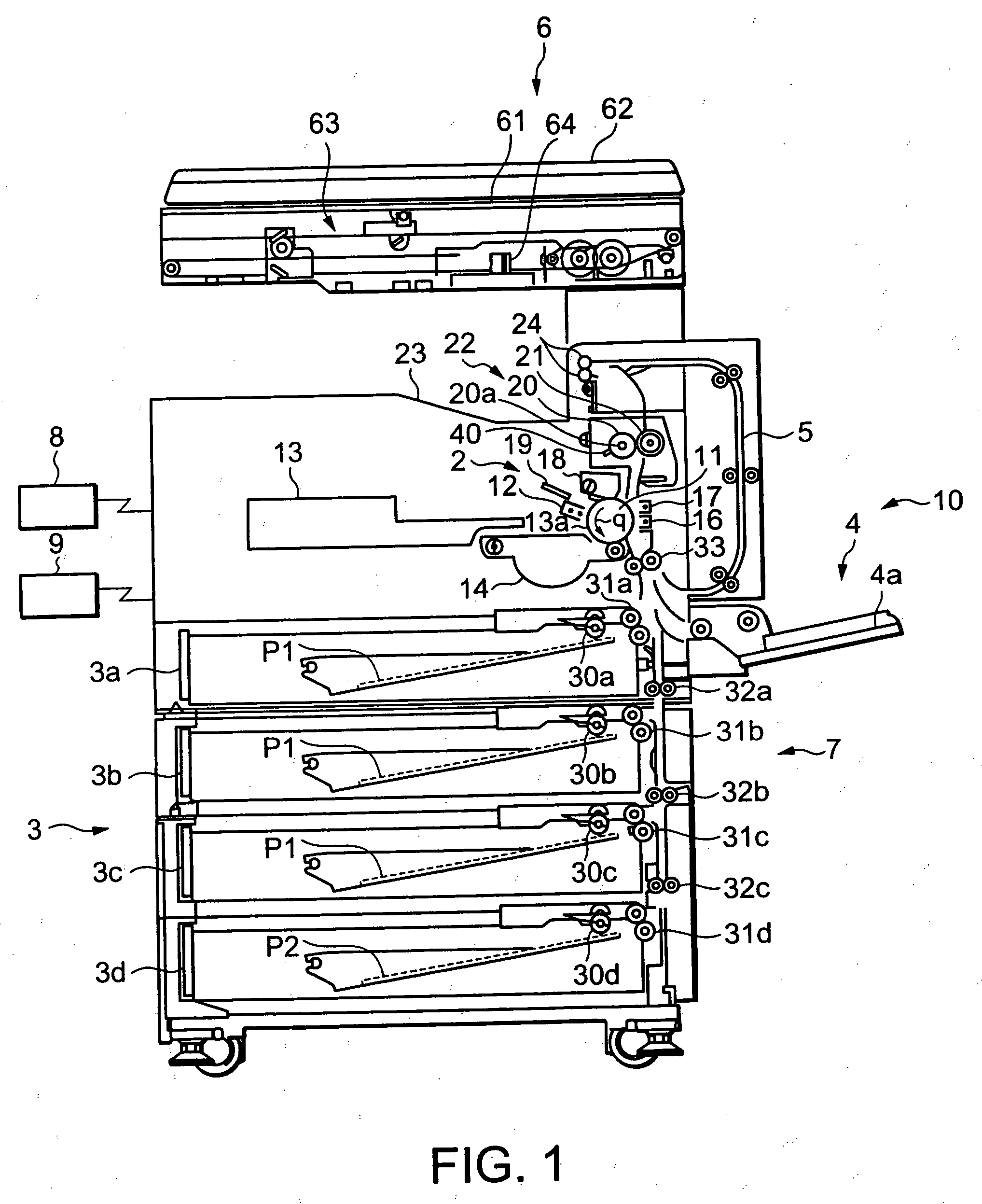
[0023]FIG. 1 is a schematic construction diagram showing a MFP 10 that is an image forming apparatus in an embodiment of this invention. This apparatus comprises an electro-photographic copying machine, a printer and a facsimile integrated in one unit. MFP10 is provided with a paper supply unit 3 comprising paper supply cassettes 3a, 3b, 3c and 3d to supply sheet paper P1 and P2 which are recording media in the direction of an image forming unit 2 which forms unfixed toner images. Further, MFP 10 is provided with a manual paper supply unit to manually supply various kinds of recording media including sheet paper P1, P2, post cards, envelops, etc. from a paper supply tray 4a and a reverse conveying path 5 to convey sheet paper P1 and P2 by reversing the front and reverse sides when images are formed on both sides of paper.

[0024] MFP 10 forms images according to image data ...


PUM


Abstract

In order to change over heating temperature and pressing force of a fixing device to heat, press and fix images on recording media, an image forming apparatus of this invention has a changeover portion to change over a heating temperature and a pressing force by the same indicating operation. Operator is not required to perform the heating temperature changeover operation and the pressing force changeover operation separately. Thus, the operability of the heat press and fixing device in changing over the fixing condition of the heating pressing and fixing device for the heat roller 20 and the press roll 21 is improved.

Description

BACKGROUND OF THE INVENTION [0001] 1. Field of the Invention [0002] This invention relates to an image forming apparatus such as copying machine, printer, facsimile, etc. equipped with a fixing device to heat, press and fix unfixed toner images or multi-functional image forming apparatus commonly provided with these image forming units and an image forming method. [0003] 2. Description of the Related Art [0004] As a fixing device that is used in electro-photographic copy machine, printer, facsimile or multi-functional peripheral (hereinafter abbreviated to MFP), there is a fixing device to heat, press and fix unfixed toner images by inserting a recording medium between fixing roller pair comprising a heating roller and a press roller or similar fixing belts. [0005] In such a fixing device, when a fixing temperature and pressing force are always at constant levels, fixation may differ depending upon such characteristics as thickness, shape or material of recording media. When heating...

Claims


Application Information

Patent Timeline
IPC IPC(8): G03G15/20
CPCG03G2215/00738G03G15/2064G03G15/2039G03G15/2032
Inventor SUZUKI, KAZUHIRO
Owner KK TOSHIBA
Why Eureka
Try Eureka