Linear motor with reduced cogging force

a linear motor and cogging force technology, applied in the field of linear motors, can solve the problems of reducing the positioning precision of the linear motor, difficult to obtain an optimal solution to reduce the cogging force, and the effect of reducing the cogging for

Active Publication Date: 2019-07-16
FANUC LTD
View PDF27 Cites 0 Cited by
  • Summary
  • Abstract
  • Description
  • Claims
  • Application Information

AI Technical Summary

Benefits of technology

[0013]In accordance with a first aspect of the present invention, provided is provided a linear motor comprising: a plurality of magnets arranged at equal intervals; and an armature arranged opposite to the magnets, the armature comprising an armature core having a plurality of teeth extending toward the magnets, the linear motor being configured to generate thrust in a thrust direction along a plane facing the magnets and the armature, wherein the teeth include a first tooth located at one end in the thrust direction and a second tooth located at the other end opposite the first tooth, the first tooth and the second tooth having different dimensions or different shapes from each other, so as to reduce cogging force generated due to a structure of the armature core at ends in the thrust direction.

Problems solved by technology

The cogging force may cause reduction in the positioning precision of the linear motor.
According to the above known art, there are many factors to be considered in determining the size of the teeth located at the ends of the armature core, so that it is difficult to obtain an optimal solution to reduce the cogging force.
Further, the known art can provide only limited effects in reducing the cogging force.

Method used


Image

  • Linear motor with reduced cogging force
  • Linear motor with reduced cogging force
  • Linear motor with reduced cogging force

Examples


Embodiment Construction

[0037]Referring to the accompanying drawings, embodiments of the present invention will be described. The constituent elements shown in the drawings are depicted in different scales as necessary for better understanding of the present invention. Further, the same or corresponding constituents are allotted with the same reference numerals.

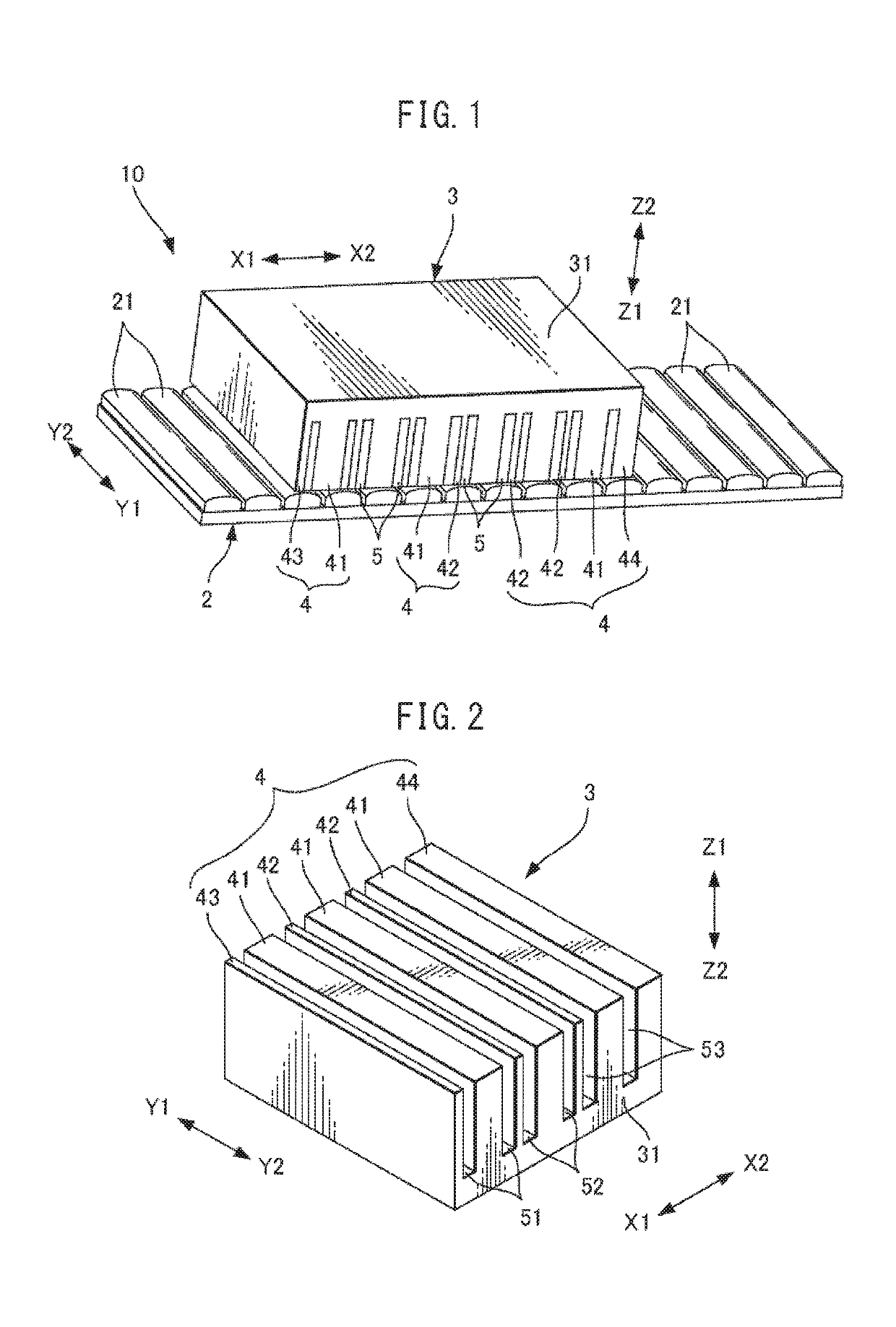
[0038]FIG. 1 is a perspective view showing a linear motor according to one embodiment. A linear motor 10 includes a magnet board 2 extending in the moving directions of the linear motor 10, indicated by arrows X1 and X2, and an armature 3 provided opposite to the magnet board 2. On a surface of the magnet board 2 facing the armature 3, elongated magnets 21 extending in directions (the directions indicated by arrows Y1 and Y2) perpendicular to the moving direction of the linear motor 10 are arranged at equal intervals. The magnets 21 are fixed to the magnet board 2 by known means such as screw fitting, adhesives, additional locking parts, or the like...


PUM


Abstract

A linear motor includes a plurality of magnets arranged at equal intervals, and an armature arranged opposite to the magnets and including an armature core having a plurality of teeth extending toward the magnets. The teeth include a first tooth located at one end in the thrust direction and a second tooth located at the other end on the opposite side. The first tooth and the second tooth have different dimensions or shapes so as to reduce cogging force generated due to the structure of the armature core at the ends in the thrust direction.

Description

BACKGROUND OF THE INVENTION[0001]1. Field of the Invention[0002]The present invention relates to a linear motor.[0003]2. Description of the Related Art[0004]Differing from rotary motors, in linear motors, the armature has a limited length in the thrust direction. As a result, it has been known that the thrust of the linear motor has a pulsating component, called cogging force, due to the structure at the opposite ends of the armature with respect to the thrust direction. The cogging force may cause reduction in the positioning precision of the linear motor. Accordingly, various measures have been proposed to reduce the cogging force, including modifying the shapes of the teeth at both ends or the like.[0005]JP2003-299342A discloses a linear motor in which the tip of the tooth located at either end in the armature moving direction is partly cut off on the side on which no neighboring tooth is formed, so that the length of the tip of the tooth with respect to the armature moving direc...

Claims


Application Information

Patent Timeline
Patent Type & Authority Patents(United States)
IPC IPC(8): H02K1/08H02K41/03H02K29/03
CPCH02K41/031H02K29/03
Inventor MAEDA, TAKUYA
Owner FANUC LTD
Why Eureka
Try Eureka