Large and small magnetic unit pole interval type stator for linear motor

A linear motor and magnetic unit technology, applied in electrical components, magnetic circuit shape/style/structure, electromechanical devices, etc., can solve the problems affecting the accuracy of the linear motor and the linear motor stuck, so as to improve the thrust and reduce the stuck. , the effect of reducing the cogging force

Pending Publication Date: 2021-11-09
江苏群科智能科技股份有限公司
View PDF0 Cites 0 Cited by
  • Summary
  • Abstract
  • Description
  • Claims
  • Application Information

AI Technical Summary

Problems solved by technology

[0003] The cogging force is generated during the motion of the linear motor. Since the mover part of the linear motor is constantly switching between the N pole and the S pole of the stator part, and the N pole and S pole on the stator are parallel to each other, at the same time There is a gap between the N pole and the S pole, and the magnetic force received by the mover when it passes between the N pole and the S pole will change greatly during the movement, and the cogging force will cause the jamming during the motion of the linear motor. Dayton, which affects the accuracy of the linear motor

Method used


Image

  • Large and small magnetic unit pole interval type stator for linear motor
  • Large and small magnetic unit pole interval type stator for linear motor
  • Large and small magnetic unit pole interval type stator for linear motor

Examples


Embodiment Construction

[0018] In order to make the purpose, technical solution and advantages of the present invention more clear, the present invention will be further described in detail below in conjunction with the accompanying drawings and embodiments. It should be understood that the specific embodiments described here are only used to explain the present invention, not to limit the present invention.

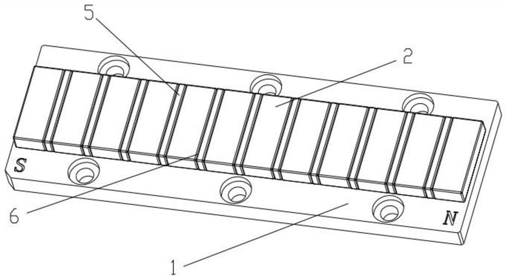
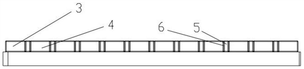
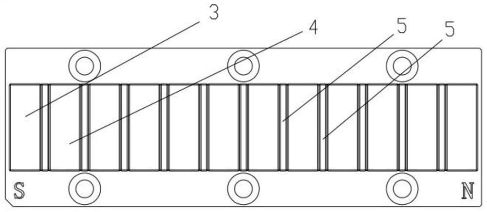
[0019] refer to Figure 1 to Figure 3 , a large and small magnetic unit pole spaced stator for a linear motor, including a placement plate 1 and a large magnetic unit 2, the large magnetic unit 2 includes S poles 4 and N poles 3, and the S poles 4 and N poles 3 are located at The placement plate 1 is distributed in a linear array along the length direction, the S poles 4 and N poles 3 are distributed alternately, the S poles 4 and N poles 3 are separated, and the S poles 4 and N poles 3 are evenly distributed on the placement plate 1 distribution, there is a gap 6 between the S pole 4 and the ...


PUM


Abstract

The invention relates to a large and small magnetic unit pole interval type stator for a linear motor, which comprises a placing plate and a large magnetic unit. The large magnetic unit comprises S poles and N poles, the S poles and the N poles are distributed in a linear array shape in the length direction of the placing plate, the S poles and the N poles are distributed in a staggered manner, the S poles and the N poles are separated, the S poles and the N poles are uniformly distributed on the placing plate, and gaps are formed between the S poles and the N poles. The stator is characterized in that small magnetic units are arranged between the S poles and the N poles, the gaps are specifically rectangular, the small magnetic units are specifically located in the gaps, and the small magnetic units are distributed on the placing plate in a linear array mode. According to the large and small magnetic unit pole interval type stator for a linear motor, the cogging force generated in the motion process of the linear motor is reduced, the jamming in the motion process of the linear motor is reduced, the precision of the linear motor is improved, the overall magnetic force of the rotor is increased, and the thrust of the linear motor is improved.

Description

technical field [0001] The invention relates to the field of linear motor stators, in particular to a stator with large and small magnetic unit pole intervals for a linear motor. Background technique [0002] A linear motor is a motor that directly generates linear motion; it can be seen as an evolution of a rotating motor; it is a transmission device that directly converts electrical energy into mechanical energy for linear motion without any intermediate conversion mechanism; a linear motor includes a stator and stator. [0003] The cogging force is generated during the motion of the linear motor. Since the mover part of the linear motor is constantly switching between the N pole and the S pole of the stator part, and the N pole and S pole on the stator are parallel to each other, at the same time There is a gap between the N pole and the S pole, and the magnetic force received by the mover when it passes between the N pole and the S pole will change greatly during the mo...

Claims


Application Information

Patent Timeline
Patent Type & Authority Applications(China)
IPC IPC(8): H02K1/17H02K1/18H02K41/02H02K41/03
CPCH02K1/17H02K1/18H02K41/02H02K41/031
Inventor 冯镜超王长征朱小瑞
Owner 江苏群科智能科技股份有限公司
Why Eureka
Try Eureka