Linear stepping motor

A linear stepping, motor technology, applied in the direction of electric components, electrical components, electromechanical devices, etc., can solve problems such as manufacturing difficulties, and achieve the effect of reducing magnetic resistance, easy winding operation, and accurate positioning

Active Publication Date: 2013-03-13
THK CO LTD
View PDF1 Cites 0 Cited by
  • Summary
  • Abstract
  • Description
  • Claims
  • Application Information

AI Technical Summary

Problems solved by technology

However, complex comb-tooth shape processing is required, or assembly (assembly) is required to maintain a constant interval between the comb teeth of the stator and the comb teeth of the moving body, which has a disadvantage of being difficult to manufacture.

Method used


Image

  • Linear stepping motor
  • Linear stepping motor
  • Linear stepping motor

Examples


Embodiment Construction

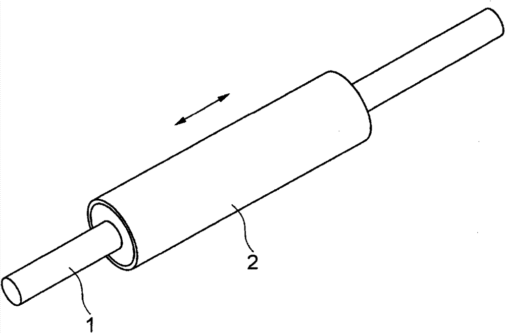
[0051] Hereinafter, embodiments of the present invention will be described in detail based on the drawings. figure 1 It is a linear stepping motor which shows 1st Embodiment of this invention. The linear stepping motor is composed of a column body 1 extending elongatedly and a cylindrical mover 2 covering the periphery of the column body 1 . The cylinder 1 functions as a field magnet of the linear stepping motor, and the mover 2 functions as an armature (motor). The cylinder 1 moves relatively linearly in the axis direction relative to the mover 2 . One of column 1 or mover 2 is fixed while the other moves.

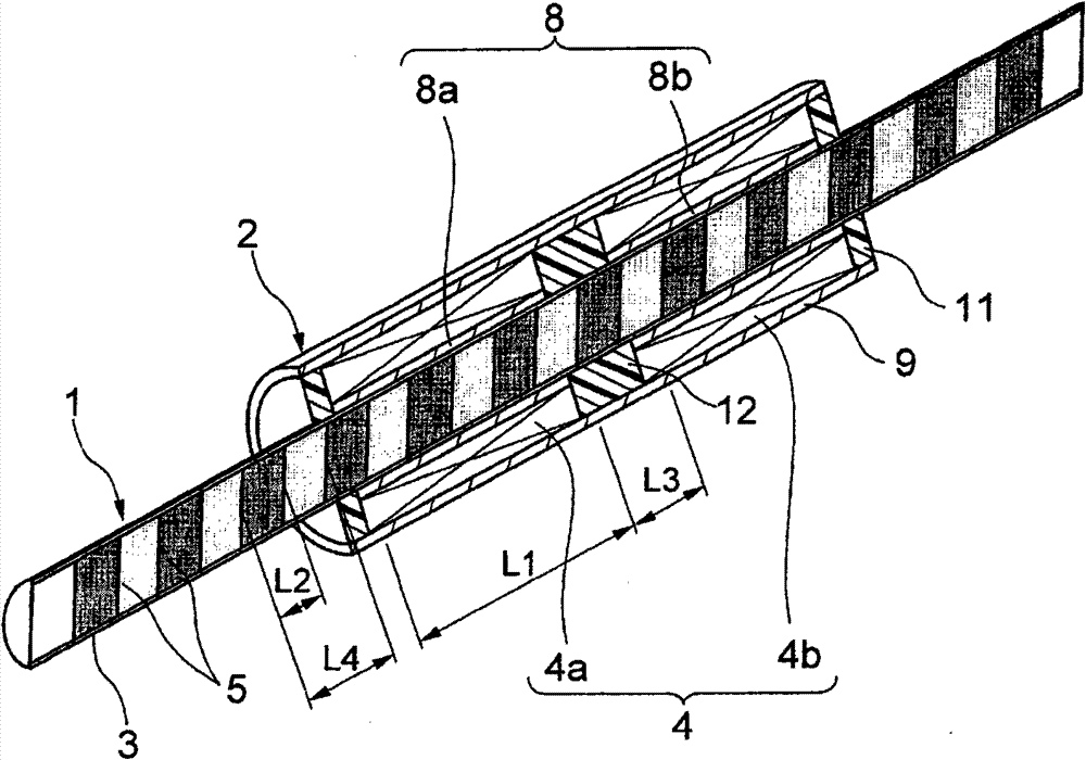
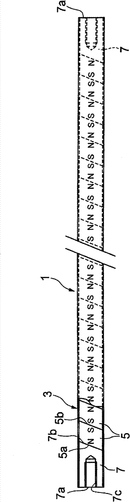
[0052] figure 2 It is a sectional view showing a linear stepping motor. In the cylinder 1, the magnetic poles of N pole and S pole are alternately magnetized in the axial direction. A two-phase coil 4 wound around the cylinder 1 with a gap is accommodated in the mover 2 . The two-phase coil 4 is constituted by a pair of coils 4a and 4b of each phase arranged side b...


PUM


Abstract

Provided is a linear stepping motor capable of simplifying the structure and achieving a high thrust. The linear stepping motor comprises a field magnet (1) having N- and S- magnetic poles magnetized alternately in an axial direction, an armature (2) having at least two-phase coils (4), and a control device for magnetizing the two-phase coils (4) and switching the coils (4) to be magnetized. At least the two-phase coils (4) enclose the field magnet (1). On the inner side of at least the two-phase coils (4), inner cores (8) of a magnetic material are arranged through a clearance from the field magnet (1). The attractions and / or repulsions between the magnetic poles generated at the two axial end portions of the exciting coils (4) and the magnetic poles of the field magnet (1) are utilized to move the field magnet (1) linearly by each predetermined step stroke relative to the armature (2).

Description

technical field [0001] The present invention relates to a linear stepping motor that makes a field magnet relatively linearly move relative to an armature at every predetermined step distance by switching excitation currents of at least two-phase coils of the armature. Background technique [0002] A stepping motor is a motor that has a function of rotating by a constant angle in proportion to the number of supplied pulses. By specifying the position and speed only by the command pulse, open-loop (open-loop) control of the rotor position and / or speed without feedback can be performed. [0003] The drive circuit of the stepping motor supplies current from a DC power supply to the stepping motor, and sequentially switches coils to be excited every time there is a command pulse. Every time the coils to be excited are switched, the rotor rotates at a fixed angle for each step. The rotary stepping motor converts the rotary motion of the rotor into a linear motion through a moti...

Claims


Application Information

Patent Timeline
Patent Type & Authority Patents(China)
IPC IPC(8): H02K41/03
CPCH02K41/03
Inventor 浅生利之山中修平
Owner THK CO LTD
Why Eureka
Try Eureka