Linear motor

A technology of linear motors and armatures, applied in the direction of electric components, electromechanical devices, electrical components, etc., can solve the problems of large pressure loss of cooling medium, difficult magnetic field to reach permanent magnets, increase of manufacturing costs, etc., to achieve efficient cooling and increase the maximum Thrust and pressure loss reduction effect

Inactive Publication Date: 2014-03-12
SANYO DENKI CO LTD
View PDF2 Cites 14 Cited by
  • Summary
  • Abstract
  • Description
  • Claims
  • Application Information

AI Technical Summary

Problems solved by technology

[0012] However, in the armature for a linear motor disclosed in Patent Document 2, the cooling pipe is long and the pressure loss of the cooling medium is large.
In addition, there is a cooling pipe on the opposite side of the magnet, so it is difficult for the magnetic field of the winding to reach the permanent magnet, and the maximum thrust is reduced
In addition, the cooling pipe in the tank must be insulated, which increases the manufacturing cost

Method used


Image

  • Linear motor
  • Linear motor
  • Linear motor

Examples


Embodiment approach 1

[0059] [Construction of linear motor]

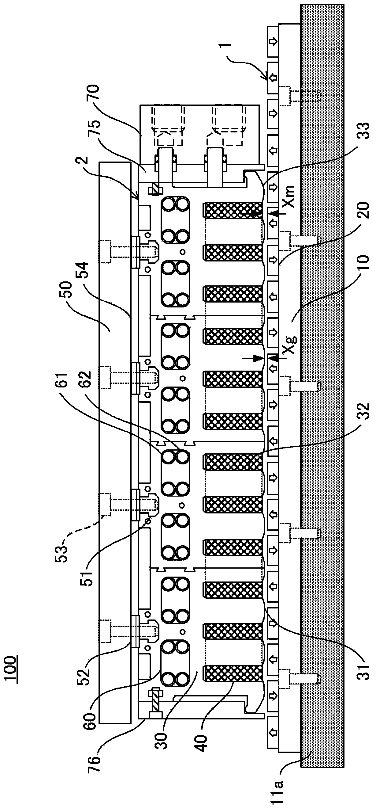
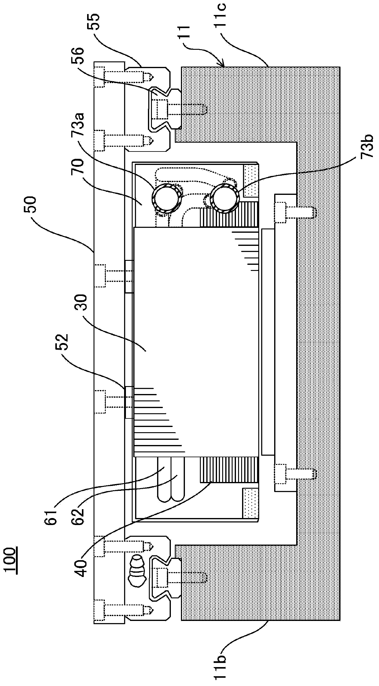
[0060] First, refer to figure 1 and figure 2 , and the configuration of the linear motor according to Embodiment 1 will be described. figure 1 It is a sectional view along the longitudinal direction of the linear motor of Embodiment 1. figure 2 It is the right side view of the linear motor of Embodiment 1.

[0061] Such as figure 1 and figure 2 As shown, the linear motor 100 according to Embodiment 1 is composed of a magnetic field generating unit 1 and an armature 2 .

[0062] The magnetic field generator 1 has a yoke 10 and a permanent magnet 20 .

[0063] The yoke 10 is a plate-shaped magnetic metal member. The yoke 10 is fixed on the bottom 11a of the assembly seat 11 having a concave cross section. The magnetic field generator 1 functions as a stator.

[0064] The yoke 10 has a function of closing the magnetic field lines from the magnetic field generator 1 to the assembly base 11 to maximize the electromagnetic inductio...

Embodiment approach 2

[0113] Then, refer to Figure 8 , Embodiment 2 will be described. Figure 8 It is a schematic cross-sectional view of an arrangement example of cooling pipes in Embodiment 1. FIG. In addition, the same code|symbol is attached|subjected to the same component as the linear motor 100 of Embodiment 1, and description is abbreviate|omitted.

[0114] Such as Figure 8 As shown, Embodiment 2 is different from Embodiment 1 in the arrangement example of cooling pipes 61 and 62 .

[0115] In the arrangement example of Embodiment 2, in the cooling pipe receiving hole 60, the upper layer side cooling pipe 61 and the lower layer side cooling pipe 62 are in contact, and the space between the cooling pipes 61, 62 is interposed with a high thermal conductivity heat transfer tube. Material 81. As a constituent material of the heat transfer material 81, for example, a material with high thermal conductivity such as copper, aluminum, or graphite is used.

[0116] Figure 8 The cross-sectio...

Embodiment approach 3

[0124] Then, refer to Figure 9 , Embodiment 3 will be described. Figure 9 It is a schematic cross-sectional view of an arrangement example of cooling pipes in Embodiment 3. FIG. In addition, the same code|symbol is attached|subjected to the same component as the linear motor 100 of Embodiment 1, and description is abbreviate|omitted.

[0125] Such as Figure 9 As shown, Embodiment 3 differs from Embodiment 1 in the arrangement example of cooling pipes 61 and 62 .

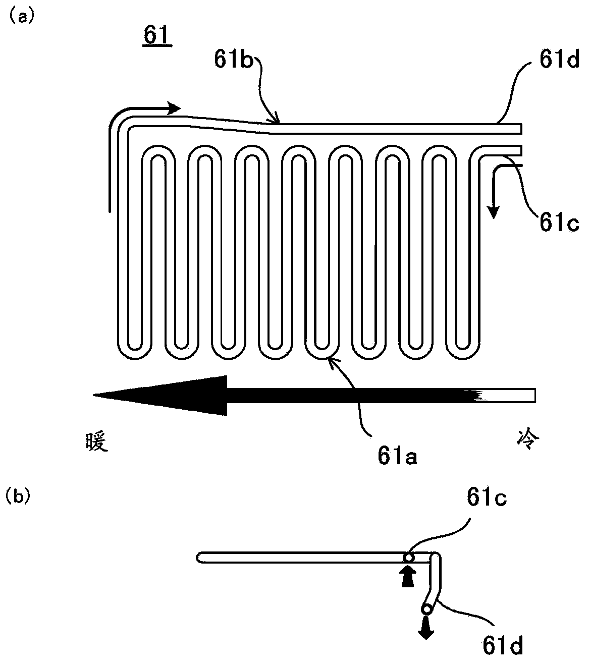
[0126] Such as Figure 7 As described in (b), when the upper and lower cooling pipes 61 and 62 are in contact, the cooling pipes 61 and 62 can easily transfer heat to the cooling medium, thereby enabling effective cooling. On the other hand, it is also easy to place the The heat is transferred to the movable table 50 side. Therefore, in order to prevent heat transfer to the movable table 50 side, in the arrangement example of the third embodiment, the upper cooling pipe 61 and the lower cooling pipe 62 are ar...


PUM


Abstract

The invention relates to a linear motor capable of realizing pressure loss of the cooling medium, enabling the uniform temperature distribution, and carrying out the high efficiency cooling. An armature(2) of a linear motor (100) includes a plurality of cooling pipe storage holes(60) formed along a longitudinal direction of a core(30), and a plurality of cooling pipes(61,62) stored vertically in the cooling pipe storage holes and having a meander shape. The cooling pipes (61,62)vertically adjacent to each other are arranged such that inlets(61c,62c) and outlets(61d,62d) of the cooling pipes are alternately connected in parallel to a refrigerant inlet(73a) and a refrigerant outlet (73b)in order to allow a refrigerant to flow in the reverse direction.

Description

technical field [0001] The present invention relates to a linear motor that linearly moves an object to be driven by electromagnetic force, and more specifically, to a linear motor provided with a cooling structure. Background technique [0002] Generally, a linear motor includes a magnetic field generator and an armature. The magnetic field generator is formed by arranging a plurality of permanent magnets adjacent to each other with different polarities. Swipe to move in the length direction of the section. [0003] In the linear motor, current flows through the winding of the armature so as to intersect with the magnetic flux generated by the permanent magnet of the magnetic field generating unit, and the winding generates a driving force in the longitudinal direction by electromagnetic induction to move the armature. [0004] In a linear motor, heat is released from the winding due to operation. Therefore, it is necessary to prevent the heat of the winding from being tra...

Claims


Application Information

Patent Timeline
Patent Type & Authority Applications(China)
IPC IPC(8): H02K41/03H02K1/32
CPCH02K1/20H02K41/02H02K41/031H02K9/20H02K2213/03
Inventor 杉田聪三泽康司宫入茂德
Owner SANYO DENKI CO LTD
Why Eureka
Try Eureka