Surgical tool for use in expanding a cannula

Inactive Publication Date: 2010-03-23
ZIMMER SPINE INC
View PDF77 Cites 81 Cited by
  • Summary
  • Abstract
  • Description
  • Claims
  • Application Information

AI Technical Summary

Benefits of technology

[0005]The present invention is a surgical tool for use in expanding a tubular structure. The tubular structure has an inner surface defining a passage through the tubular structure for receiving surgical instruments. The surgical tool includes a first leg having a first end engageable with the inner surface of the tubular structure. A second leg ha

Problems solved by technology

Due to the relatively small size of the passage into the body which is defined by the cannula, certain surgical procedures, such as p

Method used


Image

  • Surgical tool for use in expanding a cannula
  • Surgical tool for use in expanding a cannula
  • Surgical tool for use in expanding a cannula

Examples


first embodiment

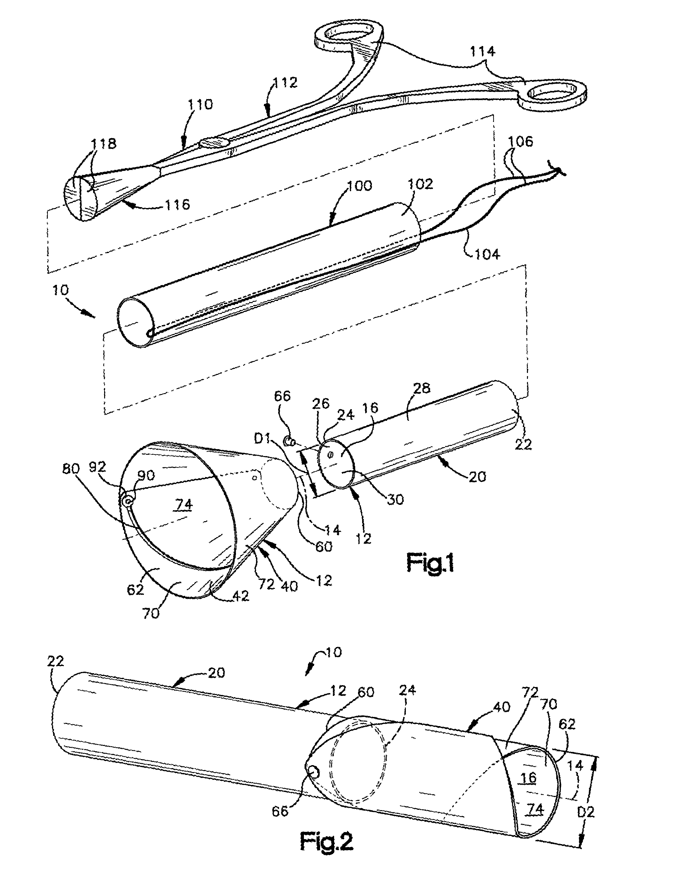
[0036]The cannula 10 further includes an actuatable device 110 for expanding the second tubular portion 40 from the contracted condition to the expanded condition. In accordance with the present invention, the actuatable device 110 comprises a manually operated expansion tool 112. The expansion tool 112 resembles a common pair of scissors and has a pair of legs 114 pivotally connected to one another. The expansion tool 112 includes a frustoconical end section 116 formed by a pair of frustoconical halves 118. Each of the frustoconical halves 118 extends from a respective one of the legs 114 of the expansion tool 112. It is contemplated that other suitable means for expanding the second tubular portion 40 toward the expanded condition could be employed, such as an inflatable balloon (not shown).

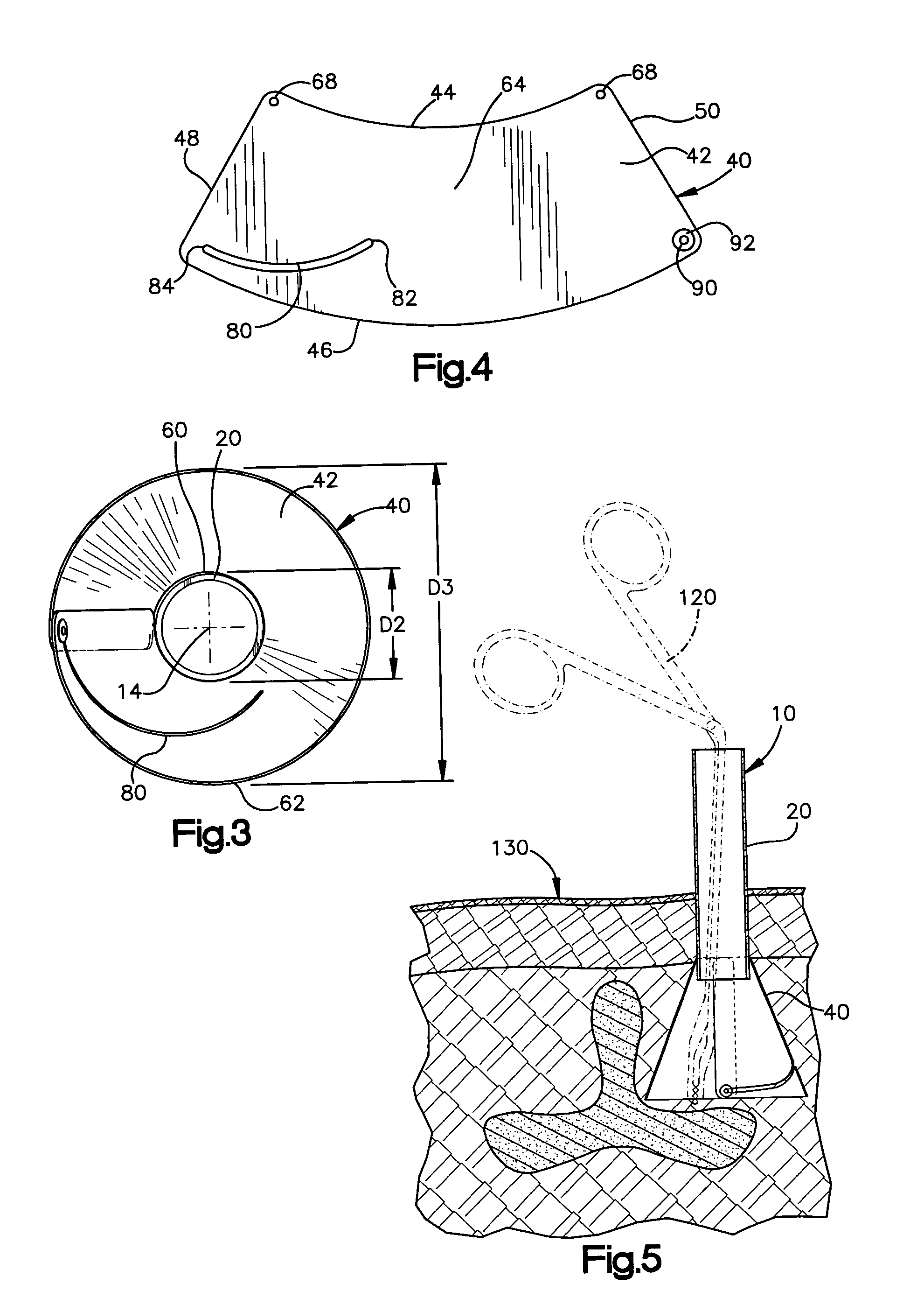
[0037]During an endoscopic surgical procedure, the cannula 10 is inserted through an incision into the body of a patient in the contracted condition. The cannula 10 is inserted through the inci...

second embodiment

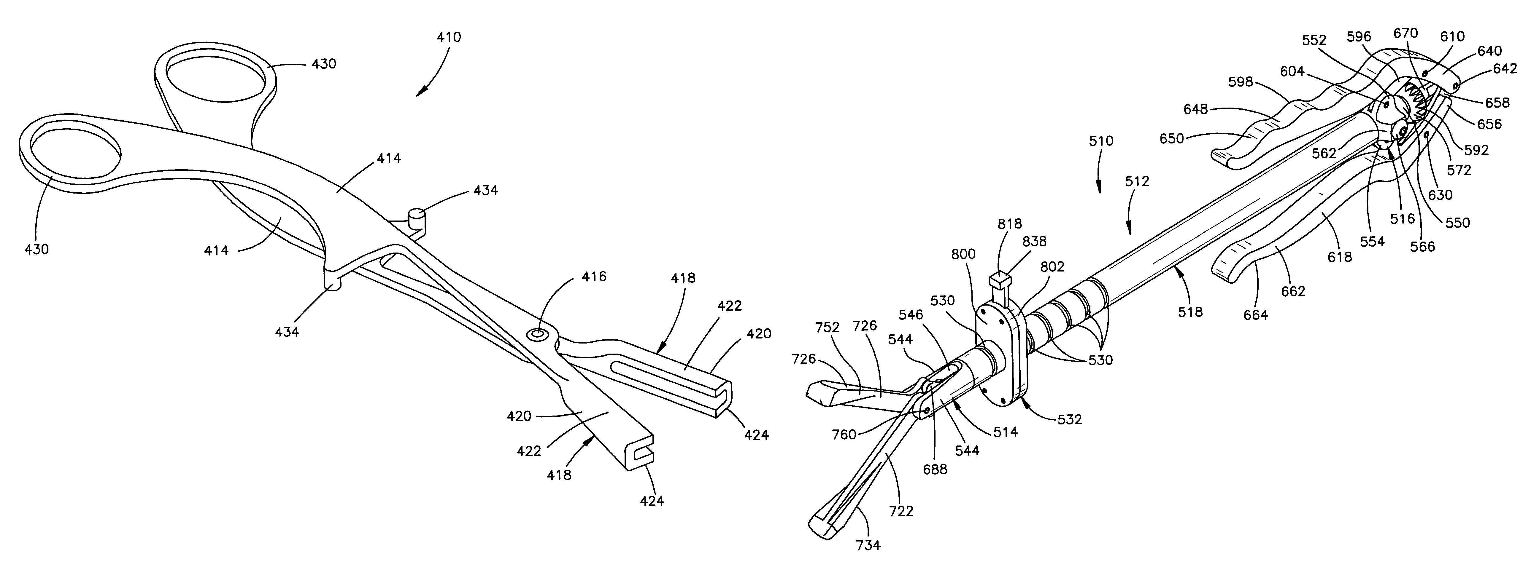
[0042]A surgical tool 410 constructed according to the present invention is illustrated in FIG. 10. The surgical tool 410 resembles a common pair of scissors and has a pair of legs 414 pivotally connected to each other by a pivot connection 416. Each of the legs 414 has an end 418 with a tapered outer surface 420. Each of the ends 418 has a generally U-shaped cross-section with outer surfaces 422 and 424. The surfaces 422 and 424 extend generally parallel to each other and transverse to the tapered surface 420.

[0043]The legs 414 have handles 430 opposite the ends 418. The handles 430 may be grasped by a surgeon to move the ends 418 away from each other. The handles 430 are moved toward each other to move the ends 418 away from each other. Each of the legs 414 has a stop 434 that engages the other leg to limit the movement of the ends 418 away from each other.

[0044]The expansion tool 410 is inserted into the passage 16 in the cannula 10 until the ends 418 are located at the second en...

third embodiment

[0045]A surgical tool 510 constructed according to the present invention is illustrated in FIGS. 11-16. The surgical tool 510 (FIGS. 11-12) includes a tubular housing 512. The housing 512 has a tubular first or distal member 514 and a tubular second or proximal member 516. A tubular intermediate member 518 interconnects the proximal and distal members 514 and 516. The distal and proximal members 514 and 516 are welded to the intermediate member 518. It is contemplated that the proximal and distal members 514 and 516 may be connected to the intermediate member 518 in any suitable manner.

[0046]The intermediate member 518 includes a first or distal end portion 522 connected to the distal member 514. The intermediate member 518 has a second or proximal end portion 524 connected to the proximal member 516. The intermediate portion 518 (FIGS. 14-15) is tubular and defines a passage 526 extending through the intermediate member. The passage 526 has a first portion 528 with a first diameter...


PUM


Abstract

A surgical tool for use in expanding a tubular structure having an inner surface defining a passage through the tubular structure for receiving surgical instruments includes a first leg having a first end engageable with the inner surface of the tubular structure. A second leg has a second end engageable with the inner surface of the tubular structure. The first and second ends are movable away from each other to apply a radially outwardly directed force to the inner surface of the tubular structure and cause expansion of the tubular structure to increase a cross-sectional area of the passage along a portion of the passage.

Description

CROSS-REFERENCE TO RELATED APPLICATION[0001]This application is a continuation-in-part of U.S. patent application Ser. No. 09 / 906,463, filed on Jul. 16, 2001now U.S. Pat. No. 6,652,553, which is a continuation-in-part of U.S. patent application Ser. No. 09 / 772,605, filed on Jan. 30, 2001 now U.S. Pat. No. 6,800,084 which is a continuation-in-part of U.S. patent application Ser. No. 09 / 137,335, filed Aug. 20, 1998, now U.S. Pat. No. 6,187,000, issued Feb. 13, 2001.FIELD OF THE INVENTION[0002]The present invention relates to a cannula or tubular structure for receiving surgical instruments for performing a surgical procedure on a body, and more specifically, to a surgical tool for use in expanding the tubular structure.BACKGROUND OF THE INVENTION[0003]Endoscopic surgical techniques allow a surgical procedure to be performed on a patient's body through a relatively small incision in the body and with a limited amount of body tissue disruption. Endoscopic surgery typically utilizes a tu...

Claims


Application Information

Patent Timeline
IPC IPC(8): A61M29/00A61B17/00A61B17/02A61B17/17A61B17/28A61B17/32A61B17/34A61B17/70
CPCA61B17/0218A61B17/1757A61B17/3421A61B17/3439A61B17/0293A61B17/1735A61B17/282A61B17/29A61B17/320016A61B2017/00238A61B2017/00261A61B2017/0046
Inventor PAGLIUCA, JAMES J.UNGER, JOHN D.ROBBINS, JAMES E.DAVISON, THOMAS W.SHER, ADAM
Owner ZIMMER SPINE INC
Why Eureka
Try Eureka