Pipe coupling

a technology of pipe coupling and pipe body, which is applied in the direction of fluid pressure sealing joints, hose connections, mechanical equipment, etc., can solve the problems of high production cost, high structural complexity of the clamping ring according to the european '896 reference, and low risk of reducing the strength of the pipe, especially for plastic pipes

Inactive Publication Date: 2000-06-06
NORMA GERMANY GMBH
View PDF6 Cites 83 Cited by
  • Summary
  • Abstract
  • Description
  • Claims
  • Application Information

AI Technical Summary

Benefits of technology

In both solutions, the clamping rings can be produced easily and inexpensively. Both clamping rings substantially completely fill the annular spaces, which are usually triangular in cross section, between the sealing gasket and the adjacent flange without requiring additional supporting parts. Therefore, the clamping rings have a relatively large cross-sectional area, with a correspondingly high strength. Thus, the clamping rings support the pipes in the axial direction against high internal pressures and are able to withstand high radial forces when the clip is being tensioned. In addition, the ribs of the second solution withstand high axial forces even though they are substantially made of plastic (as is the second ring part of the first solution).
In the first solution, the projections may be formed by a predetermined, uniform roughness on the radially inner face of the clamping rings. The radially inner face of the clamping rings may, to a considerable extent, bear over a relatively large surface against the outer circumference of the end sections of the pipes. The minute projections on the rough face form very fine grooves in the pipe material when the pipes and the clamping rings are displaced relative to one another due to high internal pressures in the pipes. Thus, the risk of reducing the strength of the pipes, especially for plastic pipes, is very low.
The second ring part is preferably attached in a groove in the radially inner circumference of the first ring part. The depth of the groove is less than the radial thickness of the second ring part. The groove, therefore, simultaneously contributes to axially securing the second ring part. Additionally, the attachment between the ring parts can be achieved in a simple manner (e.g., by adhesive bonding).

Problems solved by technology

Thus, the clamping ring according to the European '896 reference is structurally complicated and is expensive to produce.
Thus, the risk of reducing the strength of the pipes, especially for plastic pipes, is very low.

Method used


Image

  • Pipe coupling
  • Pipe coupling
  • Pipe coupling

Examples


Embodiment Construction

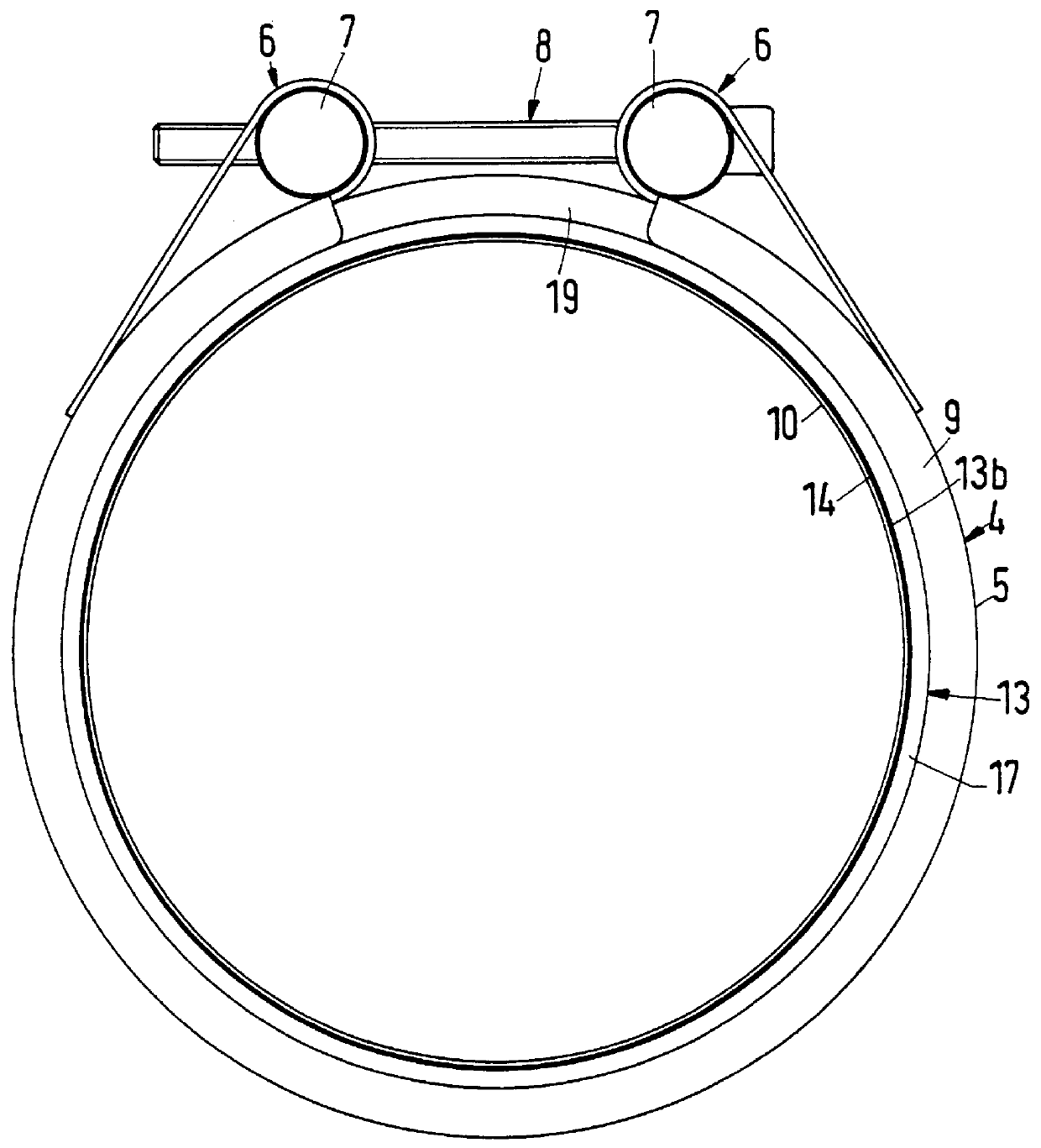
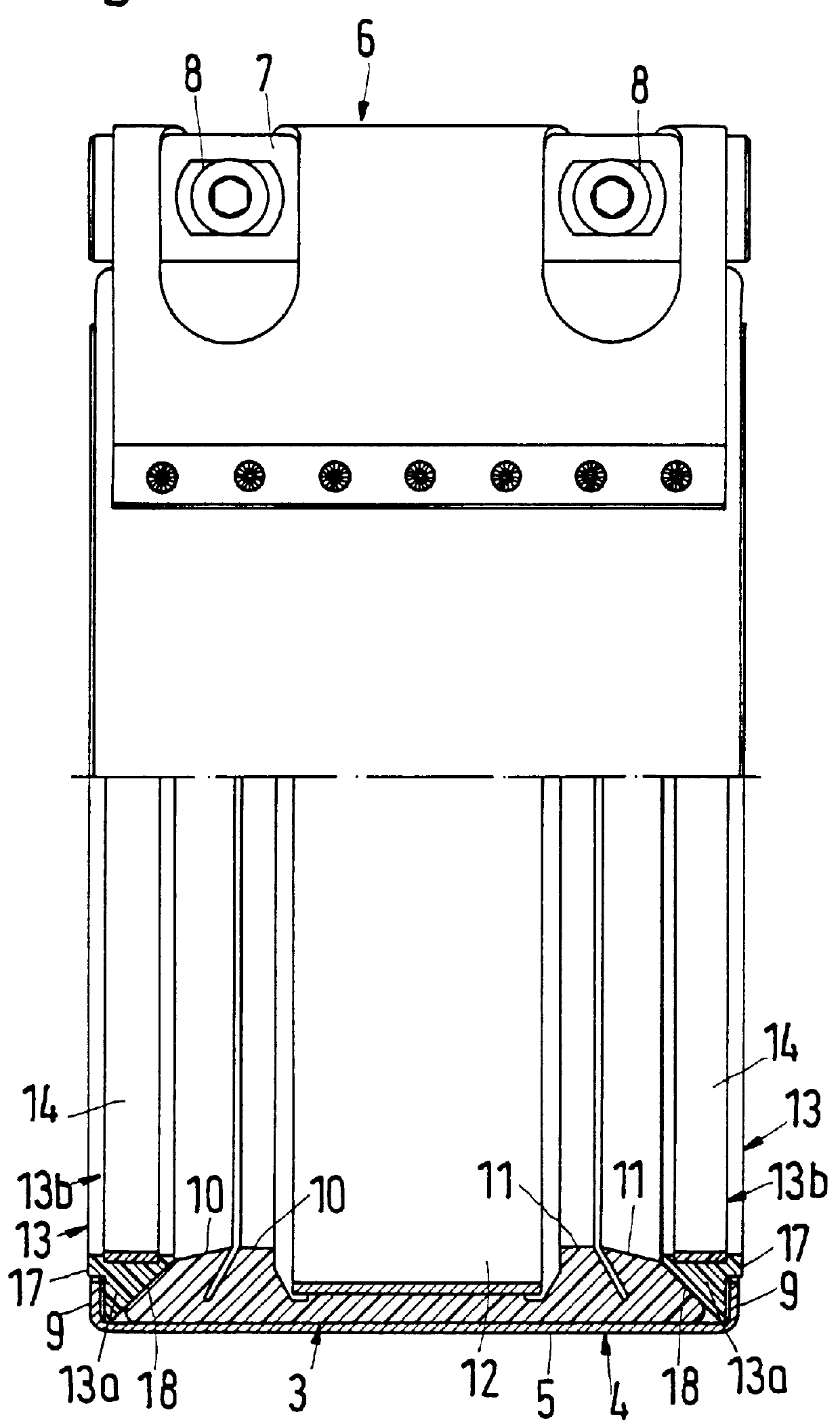
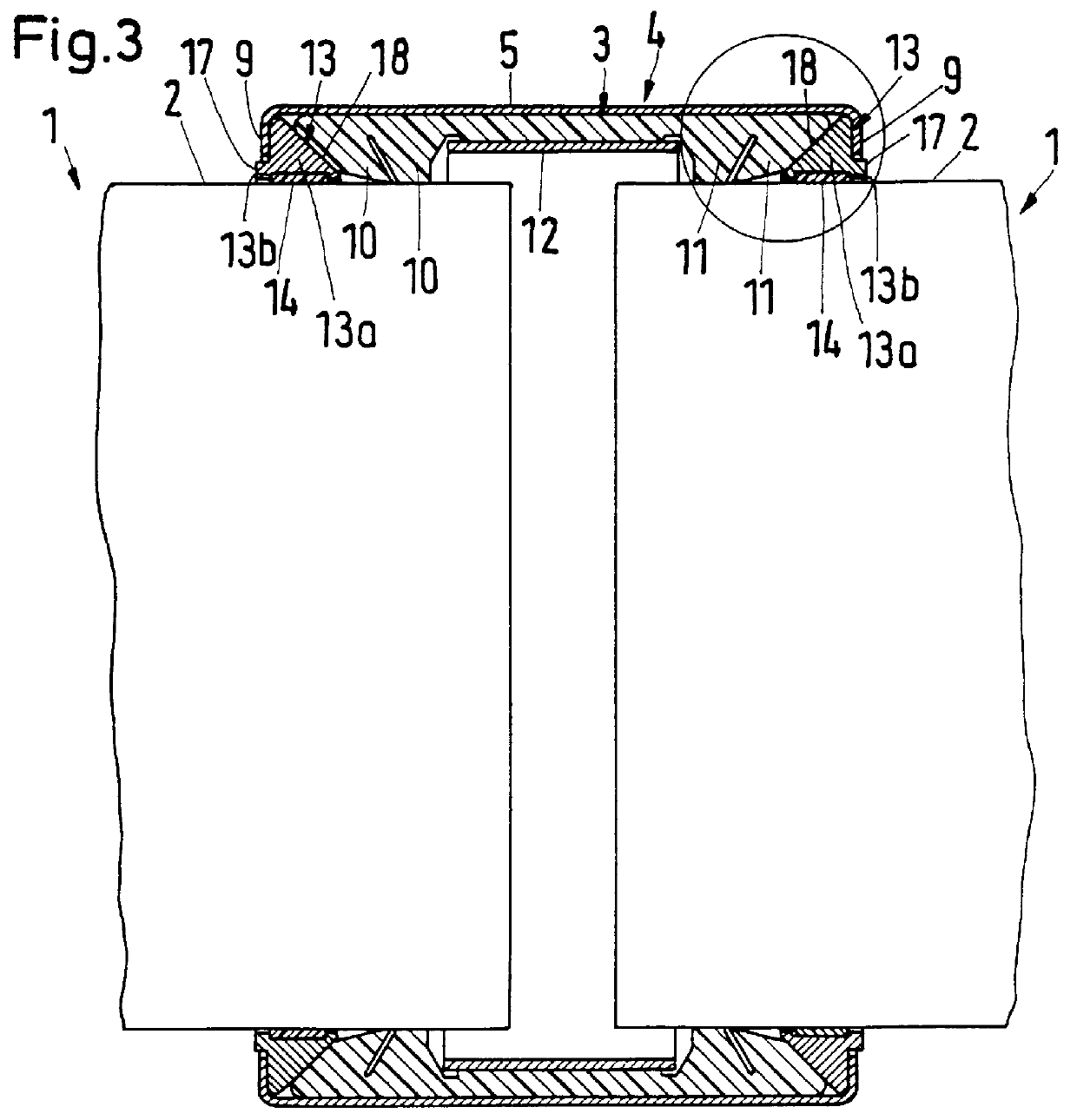
Referring now to FIGS. 1-6, a pipe coupling, for connecting pipes 1 having substantially smooth, unprofiled end sections 2, according to the present invention is illustrated. Pipes 1 may be, for example, waste water pipes, which are made from a plastic material.

The pipe coupling includes a clamping clip 4 and an elastomeric sealing gasket 3. Sealing gasket 3 holds the pipe end sections 2 in a sealed manner. Clamping clip 4, which surrounds sealing gasket 3, has a clip strap 5, which is split in the circumferential direction, thereby forming an incomplete ring. In accordance with FIG. 1, the gap between the ends of the clip strap 5 is bridged by a bridge 19. The ends of the clip strap are bent radially outwardly and back to form clamping jaws 6. Bolts 7 pass axially through clamping jaws 6. Clamping jaws 6 can be drawn together in the circumferential direction by means of a tensioning device 8, in the form of tensioning bolts, which pass through radially continuous bores in one bolt ...


PUM

PropertyMeasurementUnit
angleaaaaaaaaaa
lengthaaaaaaaaaa
angleaaaaaaaaaa

Abstract

A pipe coupling for connecting pipes having unprofiled end sections includes an elastomeric sealing gasket for holding the unprofiled pipe end sections in a sealed manner. A clamping clip surrounds the sealing gasket. The clamping clip includes a clip strap having a first end and a second end. A first clamping jaw is formed at the first end. A second clamping jaw is formed at the second end. The clamping jaws are drawn together by a tensioning device. The clip strap has radially inwardly directed projecting flanges on each of its axial ends. A first C-shaped clamping ring and a second C-shaped clamping ring are each disposed between the sealing gasket and one of the flanges. Each of the C-shaped clamping rings are supported on a radially inner side of the clip strap. Each of the C-shaped clamping rings have projections projecting from its radially inner face and, when said clip strap is tensioned, the projections of the C-shaped rings engage in the pipe material. The clamping rings are substantially made of plastic and approximately fill the space between the sealing gasket and one of the flanges. The clamping rings may be formed as a single part or from two ring parts. If formed of two parts, the radially inner part may be made of a brass alloy. The projections may be formed as encircling ribs.

Description

1. Field of the InventionThe present invention relates to a pipe coupling for connecting pipes having unprofiled end sections. The pipe coupling includes an elastomeric sealing gasket for holding the pipe end sections in a sealed manner. A clamping clip surrounds the sealing gasket. The clamping clip includes a clip strap, which is split in the circumferential direction, thereby forming an incomplete ring. The ends of the clip strap are bent radially outwardly and back to form clamping jaws, which can be drawn together by a tensioning device (e.g., a tensioning bolt). The clip strap has radially inwardly projecting flanges on each of its axial ends. A first C-shaped clamping ring and a second C-shaped clamping ring are each disposed between the sealing gasket and one of the flanges. Each of the C-shaped clamping rings are supported on the radially inner side of the clip strap. Each of the C-shaped clamping rings have projections projecting from their radially inner face. When the cl...

Claims


Application Information

Patent Timeline
Patent Type & Authority Patents(United States)
IPC IPC(8): F16L17/04F16L17/00F16L21/02F16L21/06
CPCF16L17/04F16L21/08F16L47/12Y10S285/906Y10S285/91
Inventor SCHMIDT, FRANK
Owner NORMA GERMANY GMBH
Why Eureka
Try Eureka