Large diameter optical waveguide, grating, and laser

a technology of optical waveguides and lasers, applied in the field of optical waveguides, gratings and lasers, can solve the problems of reducing optical power, coupling, and creep between fibers and tubes, and achieve the effect of reducing core to cladding coupling and increasing optical power

Inactive Publication Date: 2006-01-03
WEATHERFORD TECH HLDG LLC
View PDF62 Cites 78 Cited by
  • Summary
  • Abstract
  • Description
  • Claims
  • Application Information

AI Technical Summary

Benefits of technology

[0008]Objects of the present invention include provision of a waveguide configuration that is suitable for compression without buckling and without requiring sliding ferrules or a mecha

Problems solved by technology

However, such a technique exhibits creep between the fiber and the tube over time, or at high temperatures, or over large compression ranges.
It is also known that Bragg gratings in optical fibers may create unwanted coupling between the core and cladding modes of a f

Method used


Image

  • Large diameter optical waveguide, grating, and laser
  • Large diameter optical waveguide, grating, and laser
  • Large diameter optical waveguide, grating, and laser

Examples


Embodiment Construction

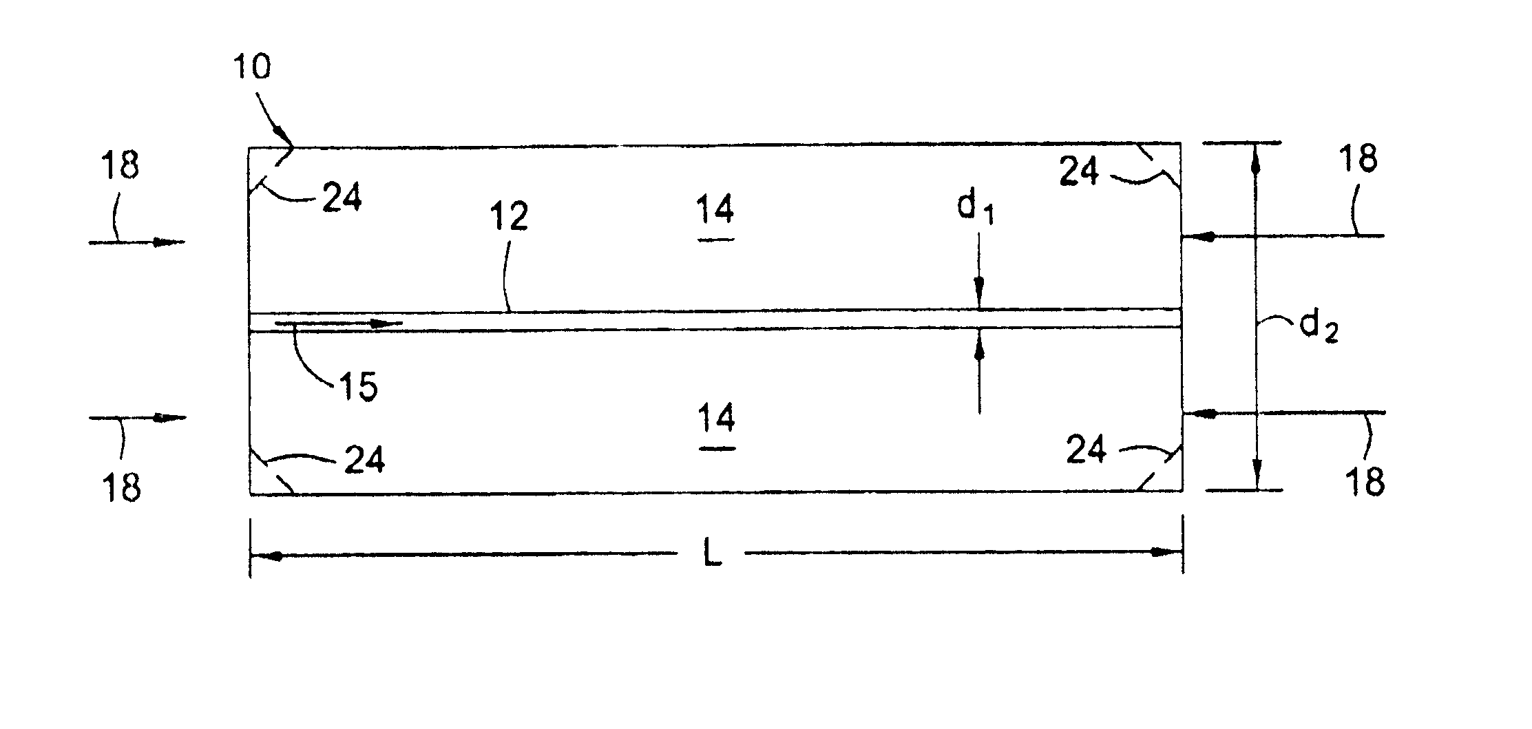
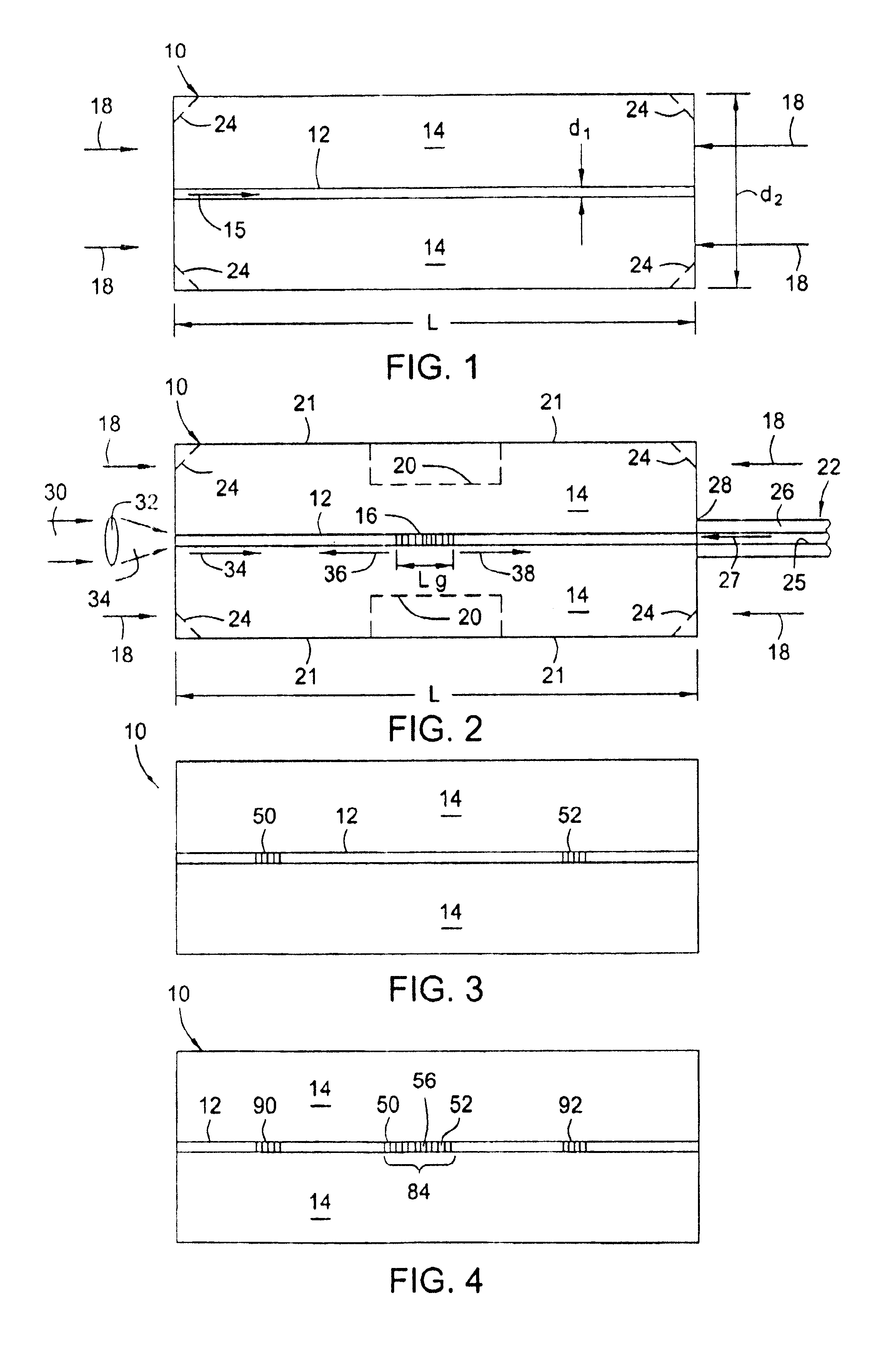
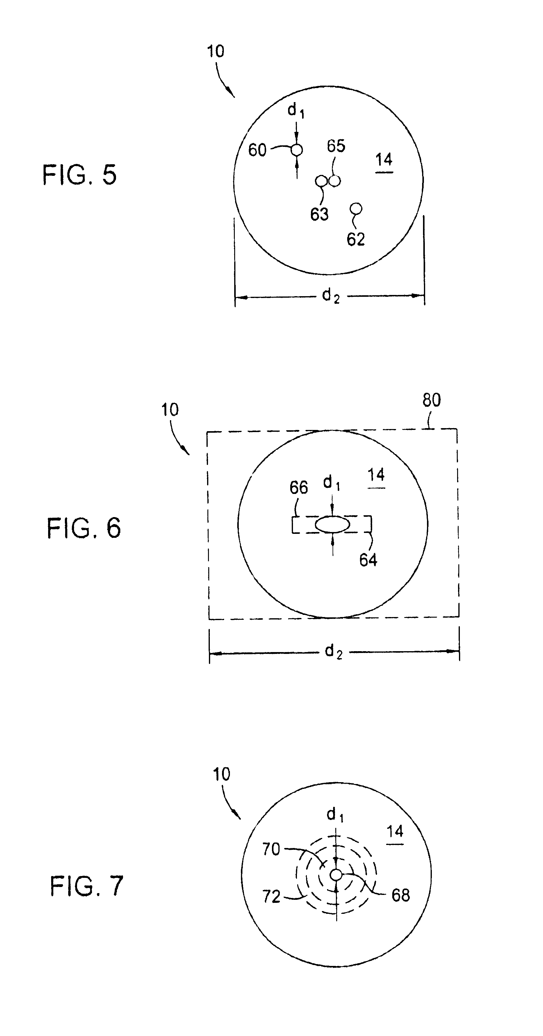
[0025]Referring to FIG. 1, a large diameter optical waveguide 10, has at least one core 12 surrounded by a cladding 14. The waveguide 10 comprises silica glass (SiO2) based material having the appropriate dopants, as is known, to allow light 15 to propagate in either direction along the core 12 and / or within the waveguide 10. The core 12 has an outer dimension d1 and the waveguide 10 has an outer dimension d2.

[0026]The cladding 14 has an outer dimension d2 of at least about 0.3 mm and the core 12 has an outer dimension d1 such that it propagates only a few spatial modes (e.g., less than about 6). For example for single spatial mode propagation, the core 12 has a substantially circular transverse cross-sectional shape with a diameter d1 less than about 12.5 microns, depending on the wavelength of light. One standard telecommunications nominal core diameter is 9 microns (and outer waveguide diameter of 125 microns). The invention will also work with larger or non-circular cores that p...


PUM


Abstract

A large diameter optical waveguide, grating, and laser includes a waveguide 10 having at least one core 12 surrounded by a cladding 14, the core propagating light in substantially a few transverse spatial modes; and having an outer waveguide dimension d2 of said waveguide being greater than about 0.3 mm. At least one Bragg grating 16 may be impressed in the waveguide 10. The waveguide 10 may be axially compressed which causes the length L of the waveguide 10 to decrease without buckling. The waveguide 10 may be used for any application where a waveguide needs to be compression tuned, e.g., compression-tuned fiber gratings and lasers or other applications. Also, the waveguide 10 exhibits lower mode coupling from the core 12 to the cladding 14 and allows for higher optical power to be used when writing gratings 16 without damaging the waveguide 10. The shape of the waveguide 10 may have other geometries (e.g., a “dogbone” shape) and/or more than one grating or pair of gratings may be used and more than one core may be used. The core and/or cladding 12,14 may be doped with a rare-earth dopant and/or may be photosensitive. At least a portion of the core 12 may be doped between a pair of gratings 50,52 to form a fiber laser or the grating 16 or may be constructed as a tunable DFB fiber laser or an interactive fiber laser within the waveguide 10. The waveguide may resemble a short “block” or a longer “cane” type, depending on the application and dimensions used.

Description

CROSS REFERENCE TO RELATED APPLICATIONS[0001]Copending U.S. patent applications Ser. No. 09 / 455,867, entitled “Bragg Grating Pressure Sensor”, and Ser. No. 09 / 456,112, entitled “Compression-Tuned Bragg Grating and Laser”, and Ser. No. 09 / 455,865, entitled “Tube-Encased Fiber Grating”, filed contemporaneously herewith, contain subject matter related to that disclosed herein.TECHNICAL FIELD[0002]This invention relates to optical waveguides, gratings and lasers and more particularly to optical waveguides, grating and laser having a large diameter.BACKGROUND ART[0003]It is known that optical fibers are stronger in compression than in tension, as described in U.S. Pat. No. 5,469,520, entitled “Compression Tuned Fiber Grating” to Morey, et al. It is also known that Bragg gratings embedded in the optical fiber may be used in compression to act as a tunable filter or tunable fiber laser, as is described in U.S. Pat. No. 5,469,520, entitled “Compression Tuned Fiber Grating” to Morey, et al a...

Claims


Application Information

Patent Timeline
IPC IPC(8): H01S3/30G02B6/122G02B6/02H01S3/00G02B6/12H01S3/06H01S3/067H01S3/10
CPCG02B6/02H01S3/06754G02B6/022G02B6/02042H01S3/06708H01S3/06729
Inventor PUTNAM, MARTIN A.BRUCATO, ROBERT N.SANDERS, PAUL E.BAILEY, TIMOTHY J.SULLIVAN, JAMES M.KERSEY, ALAN D.
Owner WEATHERFORD TECH HLDG LLC
Why Eureka
Try Eureka