Active optical phase conjugating method and apparatus

A phase and conjugation technology, applied in the field of active optical phase conjugation

Inactive Publication Date: 2007-03-21
李志扬
View PDF0 Cites 39 Cited by
  • Summary
  • Abstract
  • Description
  • Claims
  • Application Information

AI Technical Summary

Problems solved by technology

[0007] The first object of the present invention is to overcome the shortcomings of the passive optical phase conjugation method based on nonlinear optical effects, provide an active optical phase conjugation method, and realize three-dimensional high-quality imaging without

Method used


Image

  • Active optical phase conjugating method and apparatus
  • Active optical phase conjugating method and apparatus
  • Active optical phase conjugating method and apparatus

Examples


Embodiment Construction

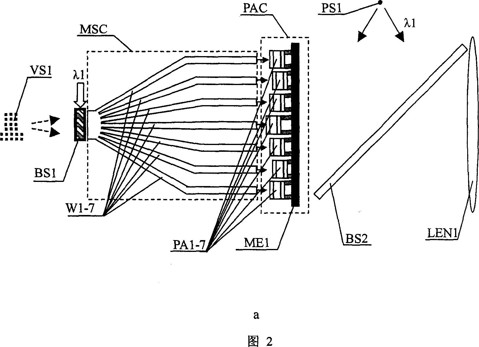
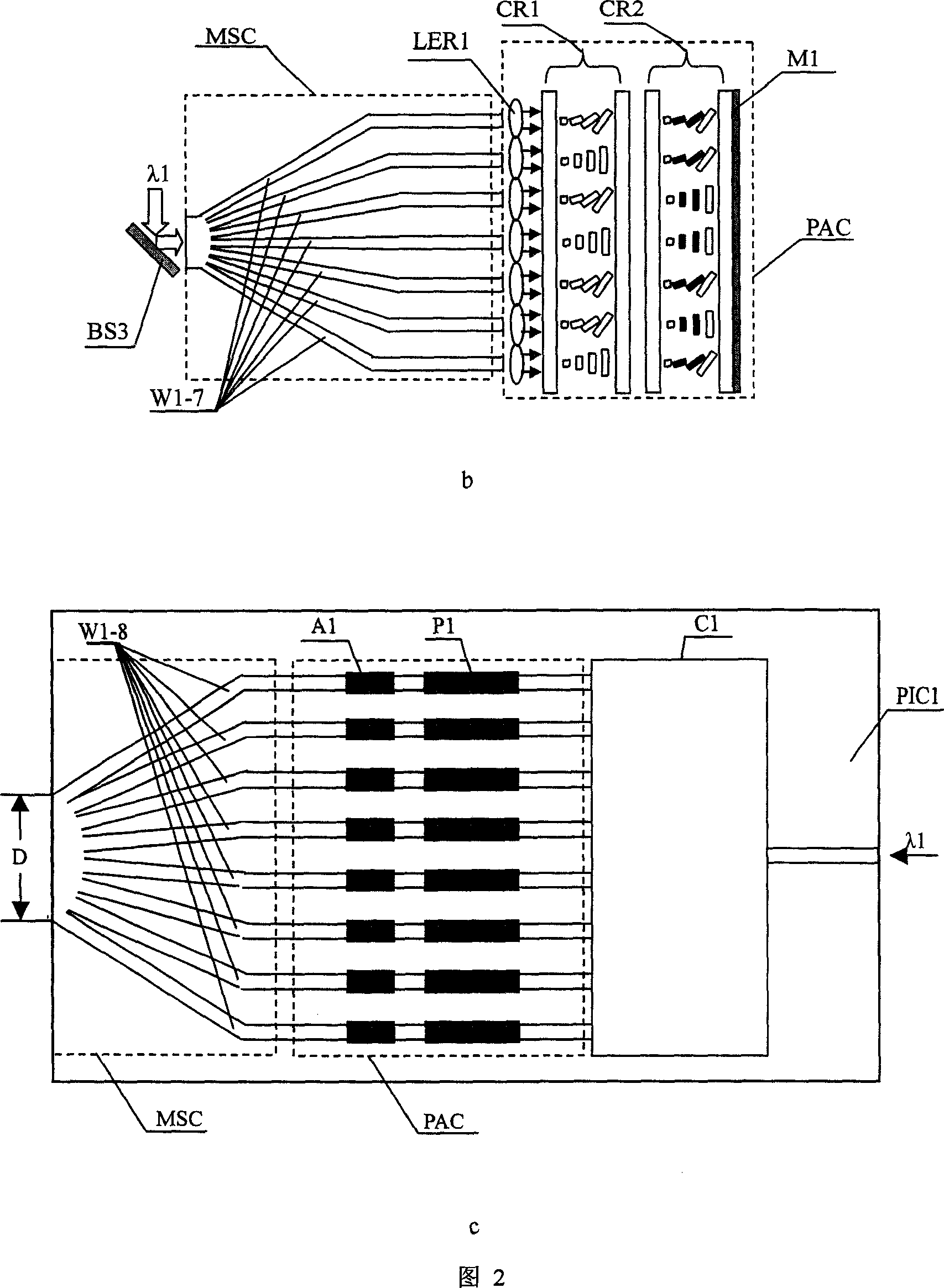
[0082] Figure 2a shows an imaging device based on active optical phase conjugation. It can be seen from Figure 2a that it consists of a mode separation / synthesis converter MSC and an optical phase conjugation regulator PAC, where the mode separation / synthesis converter MSC It is composed of optical waveguide array W1-7. The cross-sectional size of the optical waveguide W1-7 at the left end is small. It is a single-mode optical waveguide, and it is close to merge into a whole. It is polished and plated with an anti-reflection film to avoid the interference of background noise caused by reflected light. . Since the optical waveguides W1-7 are fused into a whole, the optical fields between them are coupled with each other, and the optical waveguides W1-7 at the rightmost end are placed separately, so that the optical fields between them are isolated from each other, and the right end surface of the optical waveguides W1-7 is also The anti-reflection coating is also polished and p...


PUM


Abstract

The invention relates to the active optics phase conjugate method and the imaging device, the optical switch. It constructs the mode separation/integration convertor by the optical waveguide array which is set together at one end, the optics field couples with each other; it is set separately in the other end. It leads the optical wave into the separating optical waveguide by the separation/integration convertor, then to achieve the active optics phase conjugate by adjusting the phase and the swing. It can solves the imaging problem in many limit condition such as big size, high quality, super quick focal variation, long distance and so on. So it can be used in the field of the computer-human conversation, the robot optics, the integrate circuit photoetching, information storage, the military affairs, the energy source, the biology and the light communication network.

Description

technical field [0001] The invention belongs to the technical field of optical imaging and integration, and more specifically relates to an active optical phase conjugation method, which is especially suitable for three-dimensional display and photography, high-quality diffraction-limited imaging, and precise focusing of long-distance and high-energy lasers. At the same time, it also relates to an imaging device based on active optical phase conjugation and an optical switch based on active optical phase conjugation, especially suitable for computer man-machine exchange, robot vision, integrated circuit lithography, volume information storage, military, energy, biological Network field with optical communication. Background technique [0002] The traditional optical system uses the transformation function of the optical lens to the wavefront to realize the convergence, divergence, and imaging of light waves, but it has a series of defects, such as variou...

Claims


Application Information

Patent Timeline
IPC IPC(8): G02B6/26G02B27/00
Inventor 李志扬
Owner 李志扬
Why Eureka
Try Eureka