Lubrication station oil temperature automatic control system and method

An automatic control system and lubrication station technology, applied in the direction of lubricating parts, engine lubrication, engine components, etc., can solve problems such as oil leakage of mill bearings, equipment and oil influence, difficulty in pump oil suction, etc., and achieve automatic and precise adjustment Effect

Inactive Publication Date: 2020-09-11
桂林鸿程矿山设备制造有限责任公司
View PDF5 Cites 0 Cited by
  • Summary
  • Abstract
  • Description
  • Claims
  • Application Information

AI Technical Summary

Problems solved by technology

[0002] The lubricating oil station has strict requirements on the oil temperature. If the temperature exceeds the range of 30-40°C, it will bring adverse effects to the equipment and the oil itself.
[0003] If the oil temperature exceeds 40°C, the viscosity of the oil will drop significantly first, the oil film at the sliding part will be destroyed, the friction resistance will increase, and the wear will intensify, which will cause damage to the mill bearing; if the oil temperature is too high, it will also cause The gap between the kinematic pairs of different materials changes, the gap becomes larger, the leakage increases, the pressure difference of the oil filter becomes lower, and the efficiency of the pump and the whole system will drop significantly
[0004] If the oil temperature is lower than 30°C, the viscosity of the oil will double, making it difficult for the pump to absorb oil. When the flow element is used, the characteristics of the element will change, resulting in unstable pressure and speed adjustment, resulting in oil leakage from the mill bearing
[0005] The traditional water cooling control method can only perform cooling according to the cooling processing capacity of the model selection. If the cooling water processing capacity is too large, the oil temperature may drop very low at once, which will affect the normal operation of the lubricating oil station.

Method used


Image

  • Lubrication station oil temperature automatic control system and method
  • Lubrication station oil temperature automatic control system and method
  • Lubrication station oil temperature automatic control system and method

Examples


Embodiment Construction

[0021] The principles and features of the present invention are described below in conjunction with the accompanying drawings, and the examples given are only used to explain the present invention, and are not intended to limit the scope of the present invention.

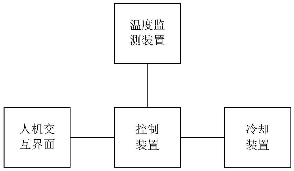
[0022] figure 1 The module block diagram of the automatic oil temperature control system of the lubrication station provided by the embodiment of the present invention.

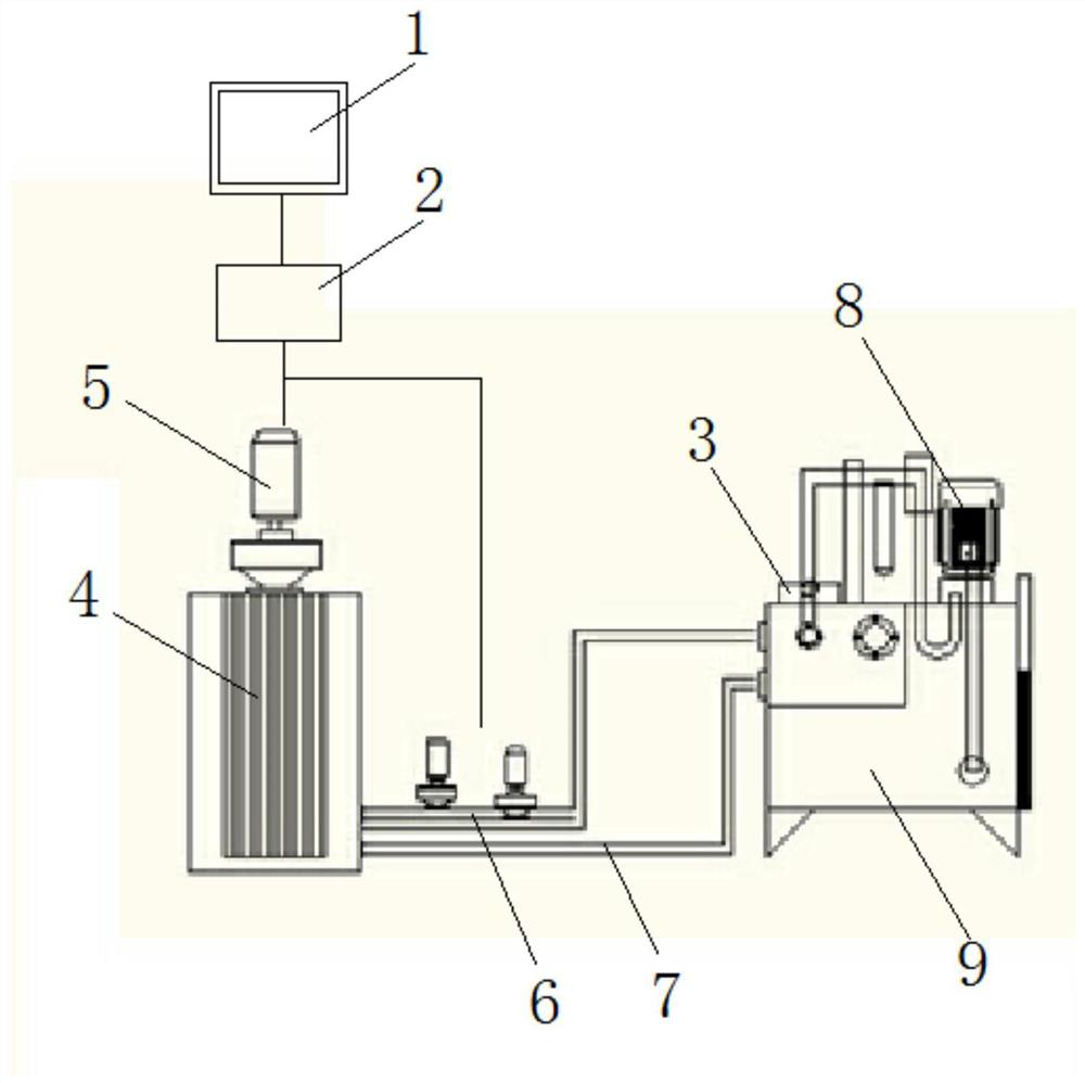
[0023] figure 2 The connection diagram of each device of the automatic oil temperature control system of the lubrication station provided by the embodiment of the present invention.

[0024] Such as Figure 1-2 As shown, a lubricating station oil temperature automatic control system, including: a human-computer interaction interface 1, a control device 2 electrically connected to the human-computer interaction interface 1, and a control device 2 electrically connected to the control device 2, which is set at the lubrication station The temperat...


PUM


Abstract

The invention provides a lubrication station oil temperature automatic control system and method. The system comprises a man-machine interaction interface, a control device connected with the man-machine interaction interface, temperature monitoring devices connected with the control device and mounted on a lubrication station and a cooling device connected with the cooling device and used for cooling the lubrication station. Through the man-machine interaction interface, reference temperature values are configured, and are sent to the control device, the temperature monitoring devices obtainreal-time temperature values, the temperature values are sent to the control device, the control device compares the real-time temperature and the reference temperature values, according to a comparison result, an adjusting instruction is generated, the adjusting instruction is sent to the cooling device, through the man-machine interaction interface, the reference temperature value most suitablefor the lubrication station is set, the control device controls the running frequency of the cooling device in real time through the real-time temperature and the reference temperature, human intervention is not needed, and automatic precise adjusting is achieved.

Description

technical field [0001] The invention mainly relates to the technical field of temperature control, in particular to an automatic oil temperature control system and method of a lubricating station. Background technique [0002] The lubricating oil station has strict requirements on the temperature of the oil. If the temperature exceeds the range of 30-40°C, it will have adverse effects on the equipment and the oil itself. [0003] If the oil temperature exceeds 40°C, the viscosity of the oil will drop significantly first, the oil film at the sliding part will be destroyed, the friction resistance will increase, and the wear will intensify, which will cause damage to the mill bearing; if the oil temperature is too high, it will also cause The gap between the kinematic pairs of different materials changes, the gap becomes larger, the leakage increases, the pressure difference of the oil filter becomes lower, and the efficiency of the pump and the whole system will drop signific...

Claims


Application Information

Patent Timeline
Patent Type & Authority Applications(China)
IPC IPC(8): F16N39/02
CPCF16N39/02
Inventor 庞锡鑫周泉锦廖专行胡亮亮
Owner 桂林鸿程矿山设备制造有限责任公司
Why Eureka
Try Eureka