
Laser Doppler Velocimeter Optical Electrical Integrated Circuits

a technology of optical electrical integrated circuits and laser dopplers, applied in the direction of optics, instruments, using reradiation, etc., can solve the problem of destroying current telecommunications pictures

Inactive Publication Date: 2013-04-04
OPTICAL AIR DATA SYST
View PDF3 Cites 36 Cited by
  • Summary
  • Abstract
  • Description
  • Claims
  • Application Information

AI Technical Summary

Benefits of technology

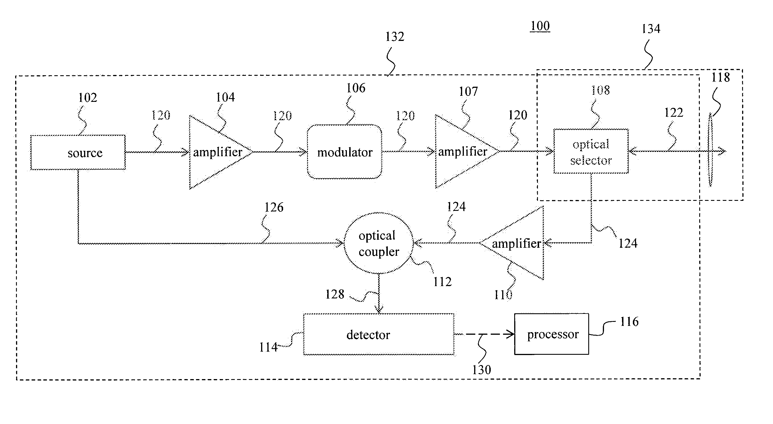
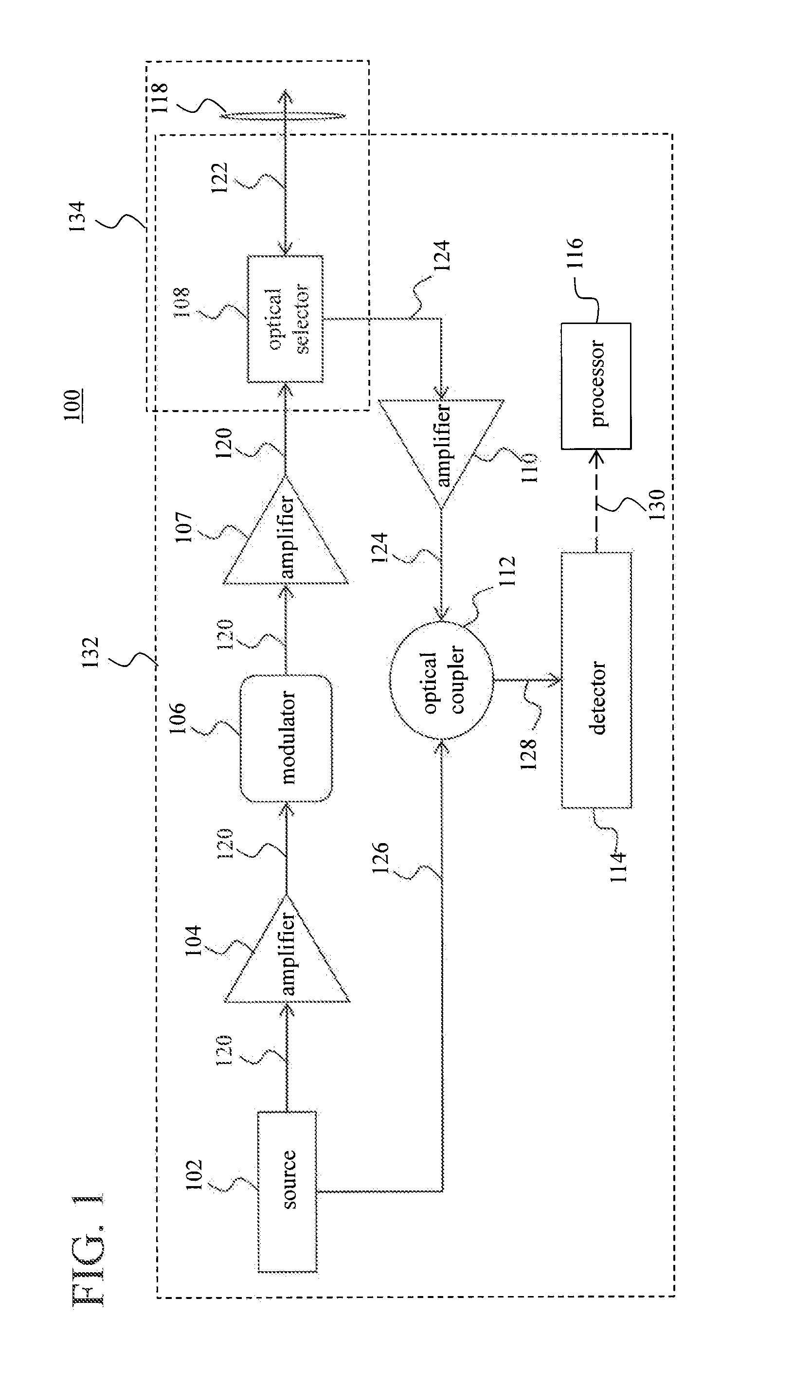
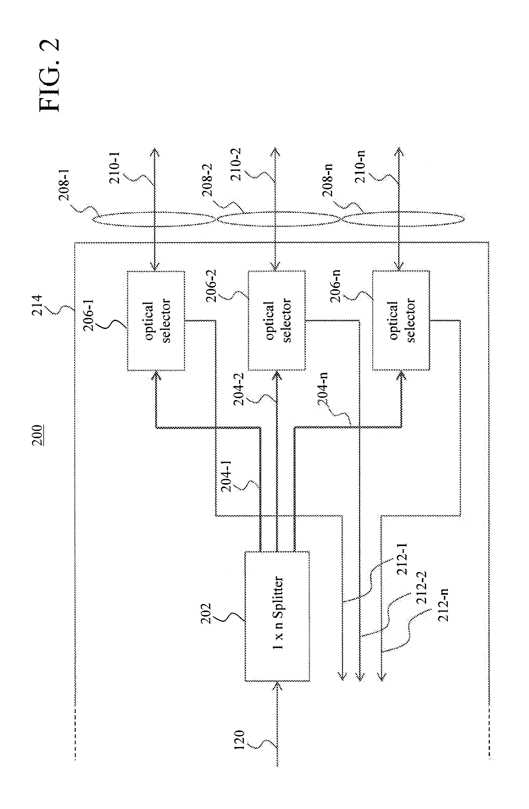
The present invention provides new manufacturing technologies and designs for optical components for a PIC operating as a LDV. Specifically, the invention includes a source of radiation, optical amplifiers, a transceiver, and optical waveguides that couple light between them. The optical amplifiers increase the optical power of the light up to at least 10 mW. Additionally, the invention includes a method for modulating a coherent light beam and receiving scattered light beams, which can be used to determine a Doppler shift. The technical effects include improved performance and efficiency of optical components in a LDV and improved accuracy and reliability in measuring the location and speed of objects using optical detection.

Problems solved by technology

Consequentially, current telecommunications PICs would be destroyed if they were used to transmit light energies occurring in LDV environments.

Method used


Image

  • Laser Doppler Velocimeter Optical Electrical Integrated Circuits
  • Laser Doppler Velocimeter Optical Electrical Integrated Circuits
  • Laser Doppler Velocimeter Optical Electrical Integrated Circuits

Examples


Embodiment Construction

[0014]This specification discloses one or more embodiments that incorporate the features of this invention. The disclosed embodiment(s) merely exemplify the invention. The scope of the invention is not limited to the disclosed embodiment(s). The invention is defined by the claims appended hereto.

[0015]The embodiment(s) described, and references in the specification to “one embodiment,”“an embodiment,”“an example embodiment,” etc., indicate that the embodiment(s) described may include a particular feature, structure, or characteristic, but every embodiment may not necessarily include the particular feature, structure, or characteristic. Moreover, such phrases are not necessarily referring to the same embodiment. Further, when a particular feature, structure; or characteristic is described in connection with an embodiment, it is understood that it is within the knowledge of one skilled in the art to effect such feature, structure, or characteristic in connection with other embodiments...


PUM

PropertyMeasurementUnit
wavelength rangeaaaaaaaaaa
poweraaaaaaaaaa

Abstract

A photonic integrated circuit and related method are presented. A photonic integrated circuit comprises a source of radiation, one or more optical amplifiers, a transceiver, and optical waveguides. The optical waveguides couple light between the source of radiation, the one or more optical amplifiers, and the transceiver. The one or more optical amplifiers are configured to increase an optical power of the light up to at least 10 mW. The photonic integrated circuit may be used to perform laser Doppler velocimeter type measurements.

Description

BACKGROUND[0001]1. Field of the Invention[0002]This disclosure relates to a system and a method to arrange optical components on a integrated circuit board, for example a laser doppler velocimeter (LDV) photonic integrated circuit (PIC).[0003]2. Background Art[0004]Similar to the transition from vacuum tubes to transistors to integrated circuits in electronic devices, optical components are becoming miniaturized through integration of components onto circuit boards. Currently, most of the development of optical component integrated circuits is being done in the telecommunications industry for a limited number of components and limited types of components. Additionally, light energy utilized for the telecommunications industry operates orders of magnitude below light energies used for what is needed in an LDV PIC. Consequentially, current telecommunications PICs would be destroyed if they were used to transmit light energies occurring in LDV environments.SUMMARY[0005]Therefore, what ...

Claims


Application Information

Patent Timeline
Patent Type & Authority Applications(United States)
IPC IPC(8): H01S3/067G02F1/11G02F1/01
CPCG01S17/58G01S7/486G01S7/484G01S7/4811G01S7/4812
Inventor DAKIN, ELIZABETH A.MAMIDIPUDI, PRIYAVADANLECLAIR, LANCECHANGKAKOTI, RUPAKCHANG, CHIA CHENDAKIN, DANIEL
Owner OPTICAL AIR DATA SYST
Learn More