[0015] In connection with an improved HUD technology that could also be used in passenger aircraft, motor vehicles, boats, ships, and other observation needs such as
simulation training centers observation displays and the like, the invention aims at achieving the following objects or requirements, such as: small weight, small installation depth, resistance against vibrations and accelerations for the intended mobile operation, utilization of the maximal display surface,
readability within a wide viewing angle within a range of about 30.degree. to about 60.degree., wherein "about" covers .+-.5.degree. unless several holograms are assembled side-by-side to obtain even larger viewing angles. A maximal surface area utilization due to an undivided display surface, a central display of critical information, variable sequential or superimposed displays of many informations, color selectivity capabilities, at least 4 million image pixels per display, for a resolution of about 0.5 angular minutes,
image frame frequency of at least 100 Hz are also aims or objects of the invention. Still another object is a new transparent, holographic display screen positioned preferably in front or integrated into the
windshield in the viewing field of the
pilot or driver and which satisfies the above requirements and is useable as an improved HUD in the above application fields. Still another object of the invention is that a
laser image
projector as a
point source, projects a
real image on the holographic display screen.
[0016] For satisfying these requirements which in part cannot be realized by a
CRT display nor by an LCD display, the invention uses preferably one or more of the special characteristics of
laser projection. These characteristics are first, a small
laser line width with a resulting large
coherence length. Second, laser projectors have a high
beam density, that is, a high light power per
solid angle, and surface area unit. The first characteristic can be used for the efficient separation of multi-color
laser light from extraneous light. The second characteristic enables an image projection with a
high resolution and a large brightness and contrast even under bright surrounding light conditions. A third feature is the
color quality of the summation of the three monochromatic laser lines in the selected
wavelength range. Such
color quality is not achievable with conventional methods. However, the invention is not limited to the use of
laser light as a projection tool. Other monochromatic or polychromatic light sources such as light emitting diodes, LEDs or spectral lamps with distinguished line spectra are also suitable for the projection purposes of the invention. These other light sources are considered to be
point light sources which, in this context, are small light sources other than a CRT or LCD
light source, which have a substantial size.
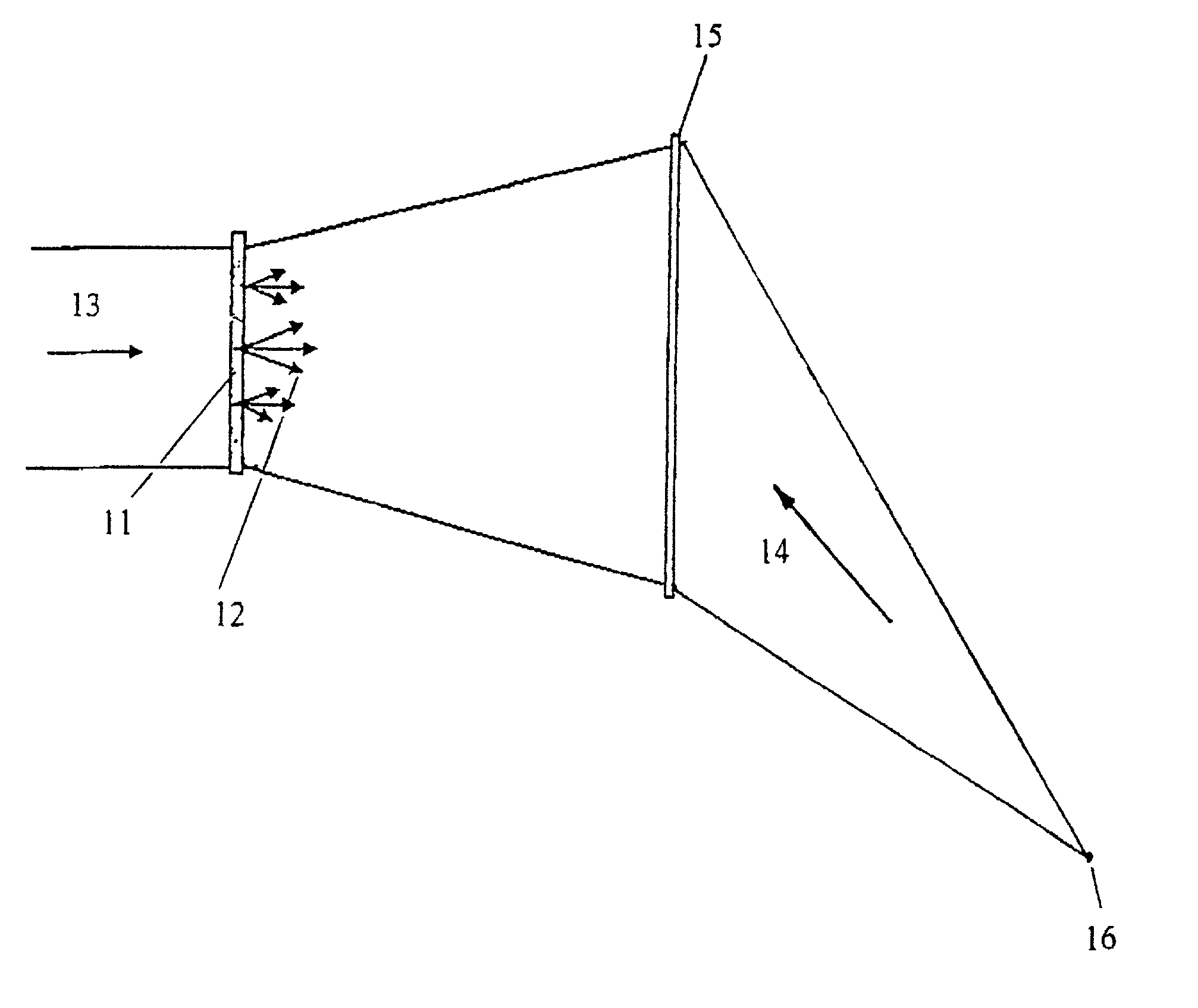
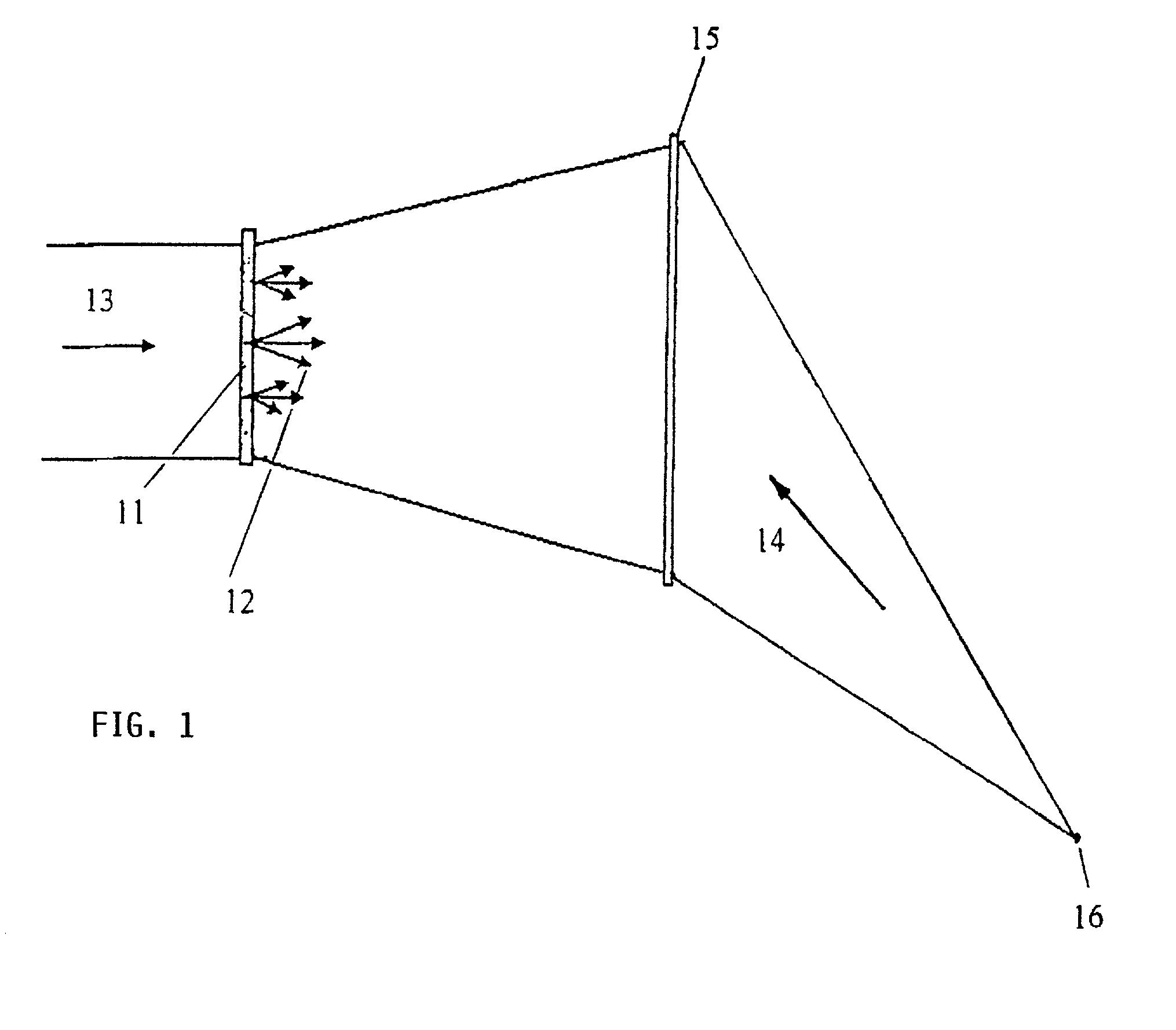
[0024] The invention uses instead of a monochromatic mirror, as in a conventional HUD, the above defined transparent holographic
projection display screen as an object hologram which is produced so that it displays a
real image for the viewer when it is illuminated by incident display
laser light or other monochromatic or polychromatic light or by a display beam from a backlight
projector, while passing
wide band light coming in through a window thereby leaving the view through that window toward the outside free. This is a very important
advantage of the invention compared to displays that project an area hologram onto a conventional
dashboard, thereby forcing the viewer to look down so that he can, at least momentarily, not look out through the
windshield. The present transparent holographic display screen is optimized so that it selectively diffracts the
narrow band laser light in one or several colors with a high efficiency in the color selectivity in a defined
solid angle while substantially transmitting unaffected the
broad band ambient light. As an object hologram this new technique provides the special
advantage that a large
image display surface can be illuminated while simultaneously making available a wide viewing angle within the range of about 30.degree. to 60.degree. or even larger than 60.degree. if several holograms are positioned side-by-side. Additionally a sharp contrast and high resolutions are achieved in combination with a high brightness display.
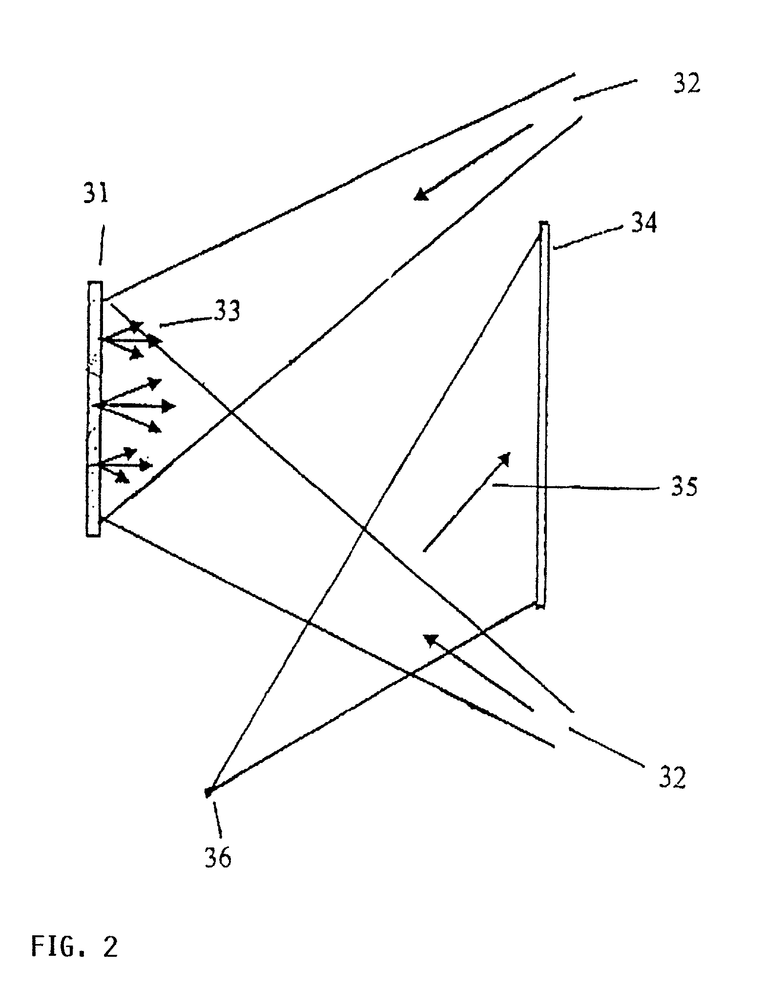
[0033] According to the invention it is suggested that the
volume hologram of the holographic image screen is produced in two steps. The first step is the same as above described to produce a primary
volume hologram with an object beam and a divergent
reference beam. However, here instead of using the
virtual image of a real display screen, the
real image of a real holographic display screen of the first recording is used as object for recording a secondary hologram to thereby optimize the recording. This use of the first or primary
volume hologram for producing as the object for the recording of the secondary hologram has the
advantage that the position of the image of the transparent holographic display screen during
reproduction or display can be adjusted to be in the plane of the secondary hologram, for example in or behind a
windshield as seen by a viewer sitting behind the windshield and looking in the travel direction. The term "behind the windshield" means inside a vehicle.
[0037] In a stack construction of the
layers on the transparent carrier plate, for example three different recording materials may be used which are adapted to the colors. In the case using three laterally arranged
layers for the different colors it is possible to additionally suppress the color "cross talk" as in a
cathode ray tube.
[0038] The invention further provides that "thick" or volume transmission holograms are used for the recording of the screen particularly in applications in which a
high selectivity of the hologram with regard to the
reproduction wavelength and the beam incidents direction is of advantage.

