Three-dimensional (3D) integrated imaging display method based on human eye tracking and integrated imaging 3D displayer

A 3D display and integrated imaging technology, applied in the direction of instrument, image communication, user/computer interaction input/output, etc., can solve the problems of image splitting, 3D display viewing angle is small, affect 3D display effect, etc., to achieve visual The effect of increasing the angle

Active Publication Date: 2013-04-03
TCL CORPORATION
View PDF5 Cites 23 Cited by
  • Summary
  • Abstract
  • Description
  • Claims
  • Application Information

AI Technical Summary

Problems solved by technology

[0003] The object of the present invention is to provide a 3D integrated imaging display method based on human eye tracking and an integrated imaging 3D display, which solves the problem that the 3D display of the existing integrated display has a small viewing angle, and the human eye is in an unused viewing area, which will cause image splitting and problems. Ghosting, affecting 3D display effect

Method used


Image

  • Three-dimensional (3D) integrated imaging display method based on human eye tracking and integrated imaging 3D displayer
  • Three-dimensional (3D) integrated imaging display method based on human eye tracking and integrated imaging 3D displayer
  • Three-dimensional (3D) integrated imaging display method based on human eye tracking and integrated imaging 3D displayer

Examples


Embodiment 1

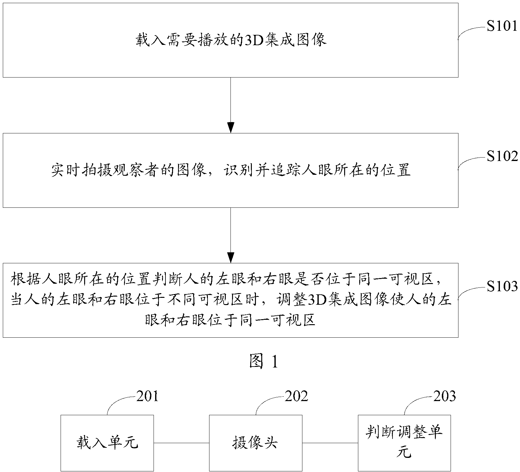
[0022] The invention provides a 3D integrated imaging display method based on human eye tracking, the method is as follows: figure 1 shown, including the following steps:

[0023] S101, load a 3D integrated image to be played.

[0024] Load the 3D integrated image to be played for the user to watch the 3D image.

[0025] S102, taking an image of the observer in real time, identifying and tracking the position of the human eye.

[0026] The image of the observer is captured by the camera in real time, and the position of the human eye is obtained according to the captured image.

[0027] S103, judge whether the left eye and the right eye of the person are in the same visual area according to the position of the human eye, and adjust the 3D integrated image so that the left eye and the right eye of the person are in different visual areas. in the same viewport.

[0028] Judging whether the left eye and the right eye are in the same visual area according to the position of th...

Embodiment 2

[0046] figure 2 It shows an integrated imaging 3D display provided by the second embodiment of the present invention, the integrated imaging 3D display is as figure 2 As shown, for the convenience of description, only the parts related to the embodiment of the present invention are shown, and the details are as follows:

[0047] The loading unit 201 is configured to load a 3D integrated image to be played.

[0048]Load the 3D integrated image to be played for the user to watch the 3D image.

[0049] The camera 202 captures images of the observer in real time, and identifies and tracks the position of the human eye.

[0050] The image of the observer is captured by the camera in real time, and the position of the human eye is obtained according to the captured image.

[0051] The judgment adjustment unit 203 is used to judge whether the left eye and the right eye of the human eye are located in the same visual area according to the position of the human eye. When the left ...

Embodiment 3

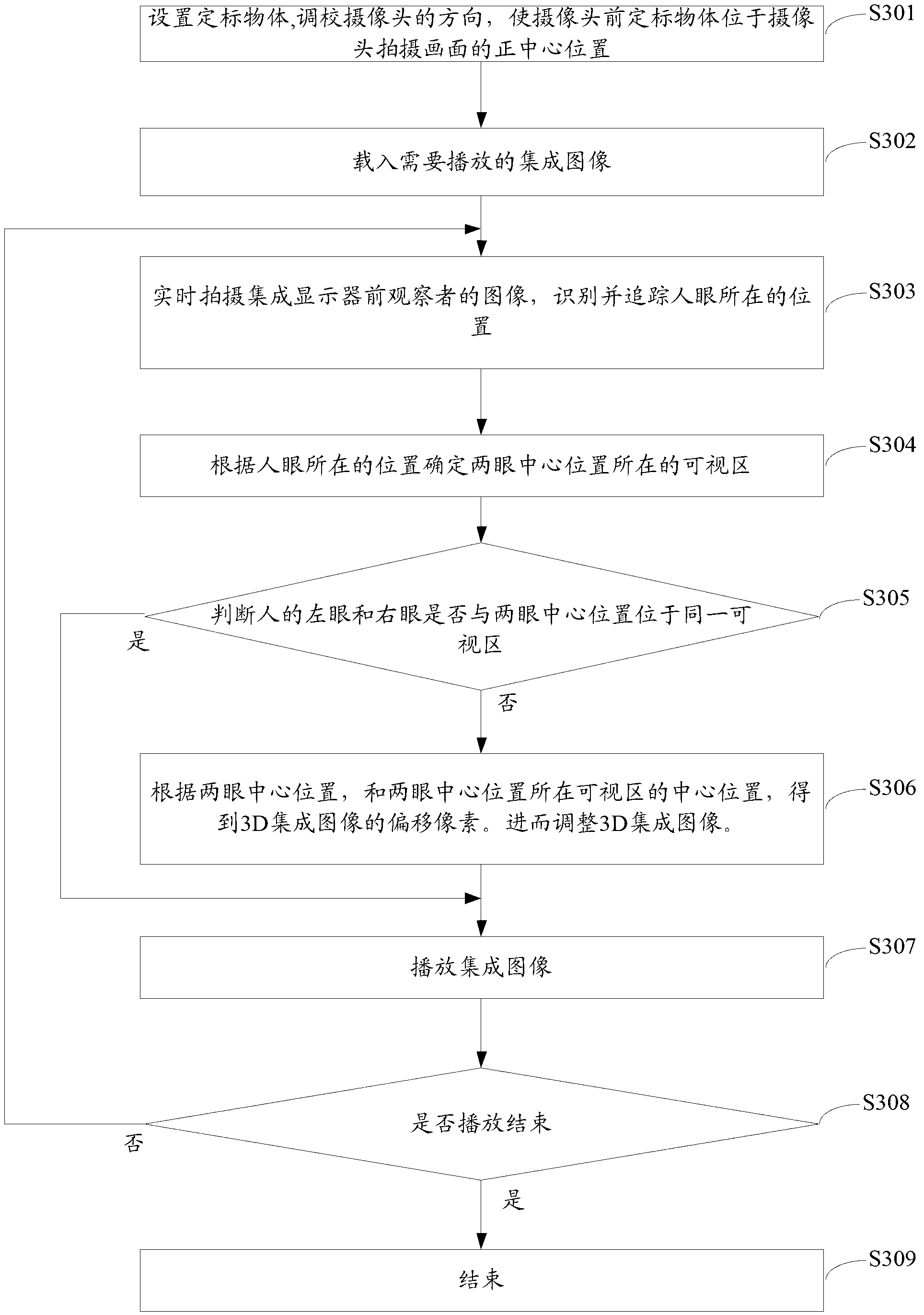
[0054] image 3 It shows the implementation flowchart of the 3D integrated imaging and display method based on human eye tracking provided by the third embodiment of the present invention. For the convenience of description, only the parts related to the embodiment of the present invention are shown, and the details are as follows:

[0055] S301 sets a calibration object, and adjusts the direction of the camera so that the calibration object in front of the camera is located at the exact center of the image captured by the camera.

[0056] Since the angle between the integrated imaging 3D display and the camera will directly affect the position of the observer captured by the calculation camera, that is, it will affect the acquired position of the human eye. Therefore, it is necessary to adjust the angle of the camera, so that the adjusted position of the camera can be easily calculated. Of course, as long as the camera alignment position is in the direction of the entire vie...


PUM


Abstract

The invention is suitable for the field of integrated imaging three-dimensional (3D) displayer and provides a 3D integrated imaging display method based on human eye tracking and an integrated imaging 3D displayer. The method comprises the following steps: loading 3D integrated images to be played; shooting images of an observer in real time and identifying and tracking the positions where human eyes are located; judging whether the positions where a left eye and a right eye of a person are located are in the same visual region or not according to the positions where human eyes are located, and adjusting the 3D integrated images to enable the left eye and the right eye of the person to be located in the same visual region when the left eye and the right eye of the person are located in different visual regions. By means of the 3D integrated imaging display method based on the human eye tracking and the integrated imaging 3D displayer, the problem that an existing integrated displayed 3D displaying visual angle is small, and the human eyes are located in the different visual regions, so that image division and image ghosting are caused and the 3D displaying effect is influenced is solved.

Description

technical field [0001] The invention belongs to the field of integrated imaging 3D displays, in particular to a 3D integrated imaging display method based on human eye tracking and an integrated imaging 3D display. Background technique [0002] The 3D display technology based on integrated imaging is a naked-eye true 3D display technology. It does not need to wear glasses, can provide true 3D images with full parallax, vivid colors, and continuous viewpoints, and can avoid visual fatigue caused by sudden changes in the disparity map in multi-view autostereoscopic display. It is an effective solution for naked-eye 3D display. Integrated imaging technology is a display technology that uses microlens arrays to record and reproduce 3D scenes. Integrated imaging 3D displays generally consist of a display screen and a microlens array. The display screen is used to display a 2D 3D integrated image, and the microlens array placed in front of the display screen is used to project d...

Claims


Application Information

Patent Timeline
Patent Type & Authority Applications(China)
IPC IPC(8): G02B27/22H04N13/00G06F3/01
Inventor 濮怡莹陈永洒付东
Owner TCL CORPORATION
Why Eureka
Try Eureka