Electro-magnetic flux switching motor

A magnetic flux switching motor and electric excitation technology, applied to the static parts of the magnetic circuit, the shape/style/structure of the magnetic circuit, the shape/style/structure of the winding conductor, etc., to achieve high sine degree, high utilization rate of excitation current, The effect of reducing the reluctance

Inactive Publication Date: 2010-07-28
NANJING UNIV OF AERONAUTICS & ASTRONAUTICS
View PDF3 Cites 14 Cited by
  • Summary
  • Abstract
  • Description
  • Claims
  • Application Information

AI Technical Summary

Problems solved by technology

[0008] In order to solve the problem of adjusting the air gap magnetic field of the magnetic flux s

Method used


Image

  • Electro-magnetic flux switching motor
  • Electro-magnetic flux switching motor
  • Electro-magnetic flux switching motor

Examples


Example Embodiment

[0017] The technical scheme of the invention will be described in detail below in conjunction with the drawings:

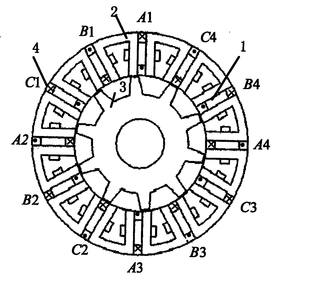
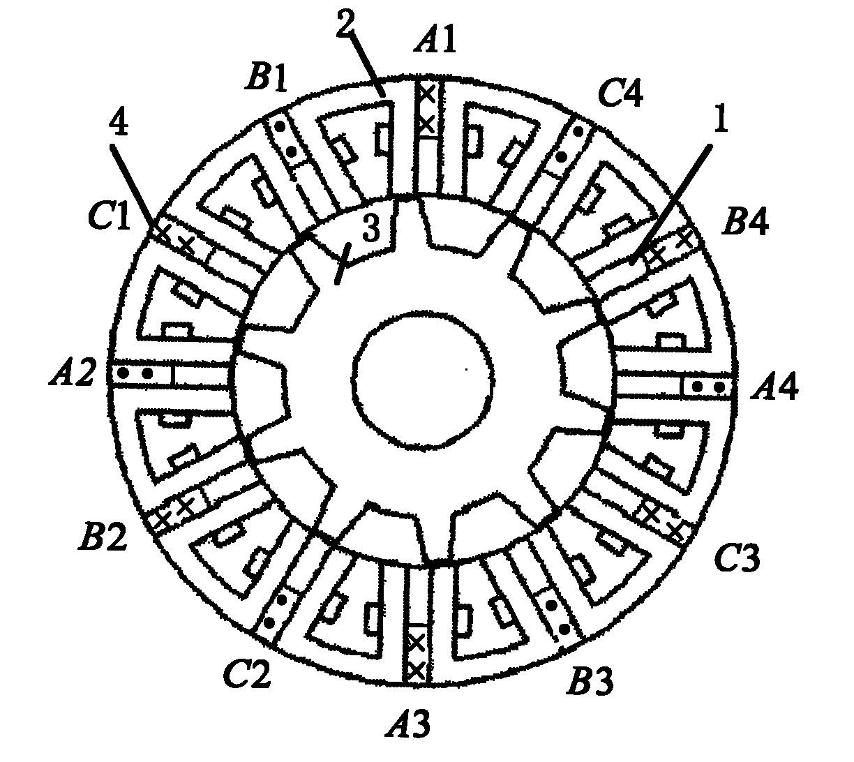
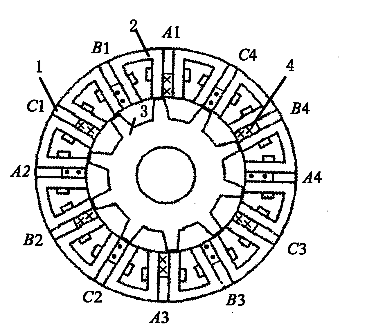
[0018] Such as figure 1 As shown, an electric excitation magnetic flux switching motor includes a salient pole stator, armature windings, excitation windings and salient pole rotors 3. The salient pole stator consists of 12 U-shaped stator iron blocks and 12 bar magnets 1 is assembled, a bar magnet 1 is embedded between every two U-shaped stator iron blocks 2, and the length of the bar magnet 1 is less than the length of the U-shaped arm of the stator iron block 2, so as to be wound on the bar magnet 1 Excitation coil; the excitation coils are all concentrated windings, 12 excitation coils are connected in series end to end to form a single-phase excitation winding; two adjacent U-shaped stator iron blocks 2 are wound with concentrated armature coils on the adjacent U-shaped arms, the first concentrated electric The armature coil A1 is radially opposite to the third ...


PUM


Abstract

The invention discloses an electro-magnetic flux switching motor belonging to the field of the electro-magnetic motors. The electro-magnetic flux switching motor comprises salient pole stators, excitation windings, armature windings and salient pole rotors, wherein the salient pole of each stator is a U-shaped iron stator block, a strip-shaped magnetizer is embedded in the space between every two U-shaped iron stator blocks, the length of the magnetizer phase is less than that of the U-shaped arm of the U-shaped iron stator block, the excitation windings are wound on the magnetizer along the radial direction of the motor, and the armature windings are wound on the two U-shaped arms connected with the magnetizer. Based on the maintenance of the high sine degree of the idle stator flux linkage and the ambipolar idle stator flux linkage waveform of the flux switching motor, the invention makes the idle air-gap field to be completely adjusted by the exciting current with a strong magnetic field adjustment capability, thereby overcoming the defect that the air-gap magnetic field of the permanent-magnetism flux switching motor is difficult to adjust.

Description

technical field [0001] The invention relates to an electric excitation magnetic flux switching motor, which belongs to the field of electric excitation motors. Background technique [0002] In the field of motors, permanent magnet motors have absolute advantages in terms of efficiency, power density, and torque density, and are more suitable for occasions that have strict requirements on volume and power. However, the permanent magnets are placed on the rotor, and there are the following problems during high-power / wide-speed operation: 1. The centrifugal force is large during high-speed rotation, and the permanent magnets must be protected; 2. The heat dissipation of the permanent magnets is difficult; 3. The magnetic field of the permanent magnets and the electric current The armature magnetic field is a series structure, and the permanent magnet is greatly affected by the armature magnetic field, and irreversible demagnetization will occur in severe cases. [0003] The st...

Claims


Application Information

Patent Timeline
IPC IPC(8): H02K1/14H02K3/28
Inventor 王宇邓智泉王晓琳
Owner NANJING UNIV OF AERONAUTICS & ASTRONAUTICS
Why Eureka
Try Eureka