Linear motor

A linear motor, magnetic pole tooth technology, applied in electrical components, electromechanical devices, electric components, etc., can solve problems such as slow moving speed, and achieve the effect of reducing magnetic resistance and eliminating high harmonic components

Active Publication Date: 2012-11-21
HITACHI METALS LTD
View PDF8 Cites 13 Cited by
  • Summary
  • Abstract
  • Description
  • Claims
  • Application Information

AI Technical Summary

Problems solved by technology

Therefore, existing technologies such as converting the output of a rotary motor into parallel motion (vertical motion) by a ball screw cannot meet the above-mentioned requirements due to the slow moving speed

Method used


Image

  • Linear motor
  • Linear motor
  • Linear motor

Examples


Embodiment )

[0170] Hereinafter, the specific configuration of the linear motor produced by the present inventors and the characteristics of the produced linear motor will be described.

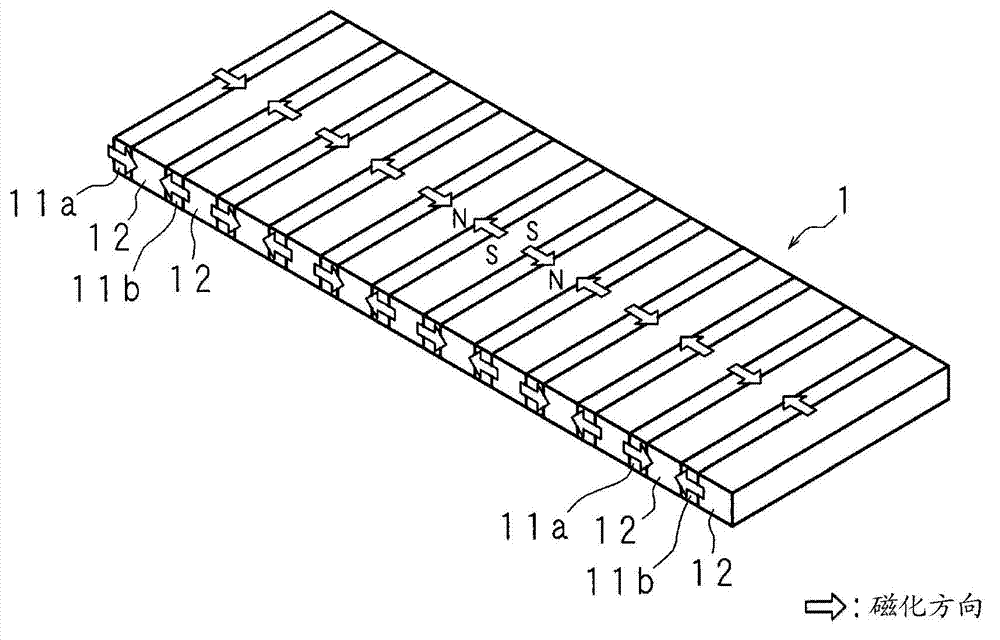
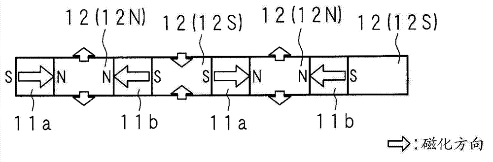
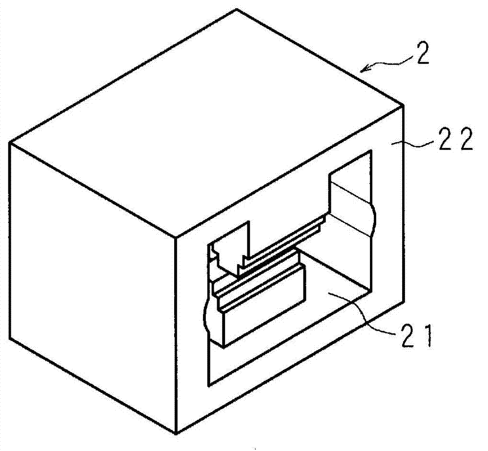
[0171] Figure 15A , 15B It is a plan view and a side view of the embodiment of the single-phase linear motor 3 of the present invention. The mover 1 penetrates the hollow portion 21 of the stator 2 to constitute the linear motor 3, wherein, in the stator 2, a plurality of magnetic pole teeth 23a and magnetic pole teeth 23b are respectively arranged in a row, and the plurality of magnetic pole teeth 23a The formed magnetic pole tooth group and the magnetic pole tooth group composed of a plurality of magnetic pole teeth 23b are respectively wound with drive coils 25a and drive coils 25b. In the mover 1, permanent magnets 11a, yokes 12, Permanent magnet 11b, yoke 12 . . . .

[0172] First, as the flat mover 1 used in the linear motor 3, a Figure 1A , 1B The mover 1 is shown in the shape of permanent ma...


PUM


Abstract

Disclosed is a linear motor which has a configuration not prone to generate magnetic flux causing short circuits between the poles of different polarity, as in monopolar drive systems, and, by means of using a bipolar drive, is capable of preventing the maximum thrust force from decreasing and has a high ratio of thrust force / magnetomotive force. A linear motor (3) is configured by a movable element (1) penetrating the hollow space of a stator (2). The movable element (1) has a permanent magnet magnetized in one of the movable directions, a soft magnetic yoke, a permanent magnet magnetized in the other of the movable directions, a soft magnetic yoke..., alternately arranged in that order. The stator (2) has multiple magnetic pole teeth arranged in a row on both sides thereof which face the movable element (1), and is formed by winding together with each drive coil (25a, 25b) the respective magnetic pole tooth group comprising multiple magnetic pole teeth.

Description

technical field [0001] The present invention relates to a linear motor formed by combining a mover having a plurality of plate-shaped permanent magnets and a stator (stator) having drive coils. Background technique [0002] High-speed movement and high-precision positioning are required for the vertical movement mechanism of the probe (contact element for inspection) in the inspection device of electronic circuit boards or the vertical movement mechanism of the pick-and-place (pick up and place the component at a predetermined position) type robot. Therefore, existing technologies such as converting the output of a rotary motor into parallel motion (vertical motion) through a ball screw cannot meet the above-mentioned requirements due to the slow moving speed. [0003] In contrast, in the above-mentioned vertical movement, a linear motor that can directly take out the output of the parallel movement is used. The above-mentioned linear motor includes a mover and a stator, an...

Claims


Application Information

Patent Timeline
Patent Type & Authority Applications(China)
IPC IPC(8): H02K41/03
CPCH02K41/03
Inventor 川上诚
Owner HITACHI METALS LTD
Why Eureka
Try Eureka