Supercharge Your Innovation With Domain-Expert AI Agents!

Stacked antenna module

Active Publication Date: 2020-04-28
INPAQ TECH
View PDF3 Cites 3 Cited by
  • Summary
  • Abstract
  • Description
  • Claims
  • Application Information

AI Technical Summary

Benefits of technology

The solution effectively decreases interference between antenna structures, increasing the main signal model and achieving improved impedance matching and gain, while maintaining insulation between the antennas.

Problems solved by technology

A top antenna structure and a bottom antenna structure of a stacked antenna module, however, may interfere with each other to lead to an interference model.

Method used


Image

  • Stacked antenna module
  • Stacked antenna module
  • Stacked antenna module

Examples


first embodiment

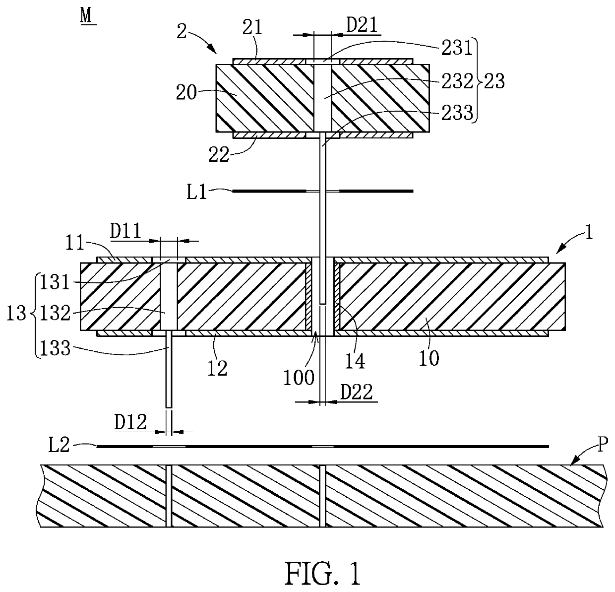
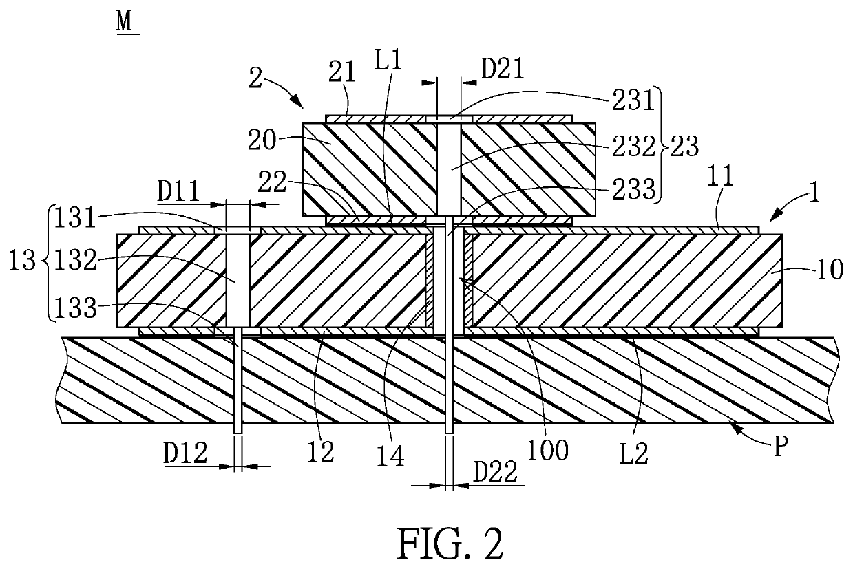
[0019]Referring to FIG. 1 to FIG. 3, the first embodiment of the present disclosure provides a stacked antenna module M, including a first antenna structure 1 and a second antenna structure 2. The first antenna structure 1 is disposed on a circuit substrate P, an insulating connection layer L1 is disposed on the first antenna structure 1, and the second antenna structure 2 is disposed on the insulating connection layer L1. That is to say, the second antenna structure 2 can be stacked on the first antenna structure 1 through the insulating connection layer L1. For example, the first antenna structure 1 may be a linear antenna, a right-hand circular polarization antenna or a left-hand circular polarization antenna, and the second antenna structure 2 may be a linear antenna, a right-hand circular polarization antenna or a left-hand circular polarization antenna, but it is not meant to limit the scope of the present disclosure. In addition, the first antenna structure 1 can be stacked o...

second embodiment

[0027]Referring to FIG. 4, the second embodiment of the present disclosure provides a stacked antenna module M, including a first antenna structure 1 and a second antenna structure 2. Comparing FIG. 4 with FIG. 3, the difference between the second embodiment and the first embodiment is as follows: in the second embodiment, the first carrier substrate 10 may be a square substrate. That is to say, the first carrier substrate 10 may be a round substrate as shown in the first embodiment (as shown in FIG. 3), or the first carrier substrate 10 may be a square substrate as shown in the second embodiment (as shown in FIG. 4), according to different requirements.

third embodiment

[0028]Referring to FIG. 5, the third embodiment of the present disclosure provides a stacked antenna module M, including a first antenna structure 1 and a second antenna structure 2. Comparing FIG. 5 with FIG. 3, the difference between the third embodiment and the first embodiment is as follows: in the third embodiment, the first antenna structure 1 includes at least two first feeding pins 13, and the second antenna structure 2 includes at least two second feeding pins 23. That is to say, the stacked antenna module M can use at least one first feeding pin 13 and at least one second feeding pin 23 as shown in the first embodiment (as shown in FIG. 3), or the stacked antenna module M can use at least two first feeding pins 13 and at least two second feeding pins 23 as shown in the third embodiment (as shown in FIG. 5).


PUM


Abstract

The present invention provides a portable electronic device and a stacked antenna module thereof. The stacked antenna module includes a first antenna structure and a second antenna structure stacked on the first antenna structure and insulated from the first antenna structure. The first antenna structure includes a first carrier substrate having at least one through hole, a surrounding insulation layer disposed inside the at least one through hole, and a first feeding pin passing through the first carrier substrate. The second antenna structure includes a second carrier substrate and a second feeding pin passing through the second carrier substrate, and the second feeding pin passes through the surrounding insulation layer without contacting the surrounding insulation layer.

Description

FIELD OF THE INVENTION[0001]The present disclosure relates to an electronic device and an antenna module thereof, and more particularly to a portable electronic device and a stacked antenna module thereof.BACKGROUND OF THE INVENTION[0002]With the development of wireless communication technologies, wireless transmission technologies are widely used in mobile information media or personal data management tools. For example, electronic products, such as notebook computers and smartphones, usually need to transmit data to other data devices or receive data from other data devices. Based on wireless transmission technologies, many structures can be simplified and many connecting wires can be avoided. To achieve the above-mentioned wireless transmission, conventional electronic products must have antennae, and most of the electronic products have inbuilt antenna devices for wireless communication. A top antenna structure and a bottom antenna structure of a stacked antenna module, however,...

Claims


Application Information

Patent Timeline
Patent Type & Authority Patents(United States)
IPC IPC(8): H01Q9/04H01L23/66H01L25/065H01L23/64H01Q1/22H01Q5/40H01Q21/28H01Q5/35
CPCH01L23/64H01Q9/045H01Q9/0414H01Q1/2283H01L25/0657H01Q5/40H01L23/66H01Q21/28H01Q5/35H01L2223/6677
Inventor CHENG, TA-FUSU, CHIH-MING
Owner INPAQ TECH
Features
  • R&D
  • Intellectual Property
  • Life Sciences
  • Materials
  • Tech Scout
  • Unparalleled Data Quality
  • Higher Quality Content
  • 60% Fewer Hallucinations
Learn More