Image display system, terminal, method, and program for displaying image associated with position and orientation

a technology of image display system and position orientation, applied in image data processing, still image data retrieval, instruments, etc., can solve problems such as difficulty in reporting all, and achieve the effect of easy acquisition

Active Publication Date: 2021-02-16
NEC CORP
View PDF18 Cites 0 Cited by
  • Summary
  • Abstract
  • Description
  • Claims
  • Application Information

AI Technical Summary

Benefits of technology

[0015]According to the present invention, since an image stored in the past is acquired based on the position and the orientation of a mobile terminal, it is possible to easily acquire and display an image corresponding to a particular place which the user having the mobile terminal faces.

Problems solved by technology

It is difficult to report all, to the personnel who perform check immediately before an important person passes by, whether or not it is an object that has been confirmed to be usually placed.
Thus, when a suspicious object has been placed after the previous survey, the personnel who check immediately before the important person passes by may not notice the suspicious object or may overreact to the object and take time for check even though it is not a suspicious object.

Method used


Image

  • Image display system, terminal, method, and program for displaying image associated with position and orientation
  • Image display system, terminal, method, and program for displaying image associated with position and orientation
  • Image display system, terminal, method, and program for displaying image associated with position and orientation

Examples


first example embodiment

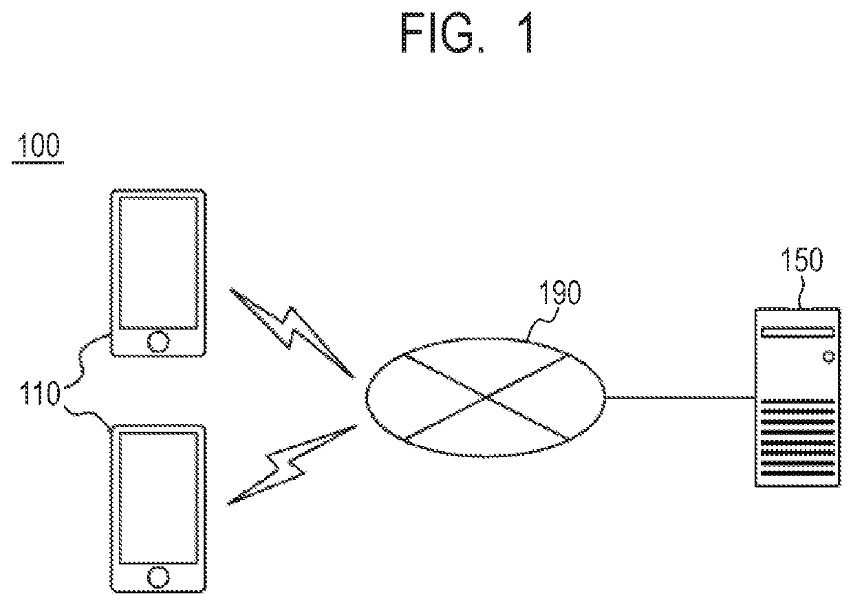
[0032]FIG. 1 is a schematic diagram of an image display system 100 according to the present example embodiment. The image display system 100 has a mobile terminal 110 and a server 150. The mobile terminal 110 and the server 150 are connected to each other via wired connection or wireless connection via a network 190 such as the Internet. The image display system 100 may include devices such as another server, another mobile terminal, or the like. The mobile terminal 110 is a terminal that is carried by a customer and has an image capture function using a camera and a function of displaying an image acquired from the server 150. The server 150 is a server that is installed at any location and performs storage and acquisition of an image.

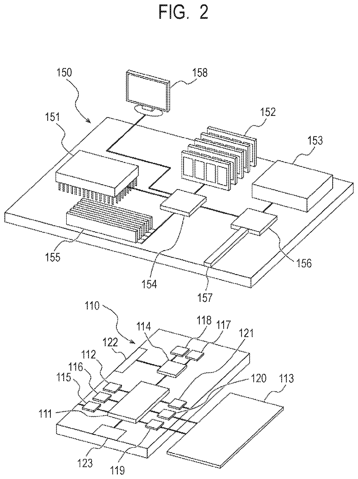
[0033]FIG. 2 is a general configuration diagram of the mobile terminal 110 and the server 150 according to the present example embodiment. Note that each of the mobile terminal 110 and the server 150 may be formed of a single device, or may be formed ...

second example embodiment

[0089]The present example embodiment provides a method for more accurately displaying a past image corresponding to the current captured range of the camera 115, that is, the user's field of view. The configuration of the image display system 100 according to the present example embodiment is the same as that of the first example embodiment, and the only difference is in a calculation method of a similarity degree. FIG. 9 is a schematic diagram illustrating positions and orientations of a current image and a past image. In FIG. 9, the positions and orientations of the current image and the past image are represented by arrows on an x-y plane with any point being the origin. The position of an arrow illustrates the position of the current image or the past image, the direction of an arrow illustrates the orientation of the current image or the past image. The positive direction in the y-axis is here defined as the north direction.

[0090]The orientation of the current image D1 is the n...

third example embodiment

[0093]The present example embodiment provides a method for more accurately displaying a past image corresponding to a current captured range of the camera 115, that is, the user's field of view. The configuration of the image display system 100 according to the present example embodiment is the same as that of the first example embodiment, and the only difference is in a calculation method of a similarity degree. FIG. 10 is a schematic diagram illustrating positions and orientations of a current image and a past image. In FIG. 10, the positions and orientations of the current image and the past image are represented by arrows on an x-y plane with any point being the origin, respectively. The position of an arrow illustrates the position of the current image or the past image, the direction of an arrow illustrates the orientation of the current image or the past image. The positive direction in the y-axis is here defined as the north direction.

[0094]The orientation of all the current...


PUM


Abstract

The present invention provides an image display system, a terminal, a method, and a program that can quickly and accurately display an image corresponding to a particular place. An image display system according to one example embodiment of the present invention includes: an information acquisition unit that acquires information including a position and an orientation of a mobile terminal; and an image acquisition unit that, based on the position and the orientation of the mobile terminal and a position and an orientation associated with an image stored in a storage device in the past, acquires the image.

Description

CROSS REFERENCE TO RELATED APPLICATIONS[0001]This application is a National Stage of International Application No. PCT / JP2017 / 006864, filed on Feb. 23, 2017, which claims priority from Japanese Patent Application No. 2016-035650, filed on Feb. 26, 2016, the disclosure of which is incorporated herein by reference in its entirety.TECHNICAL FIELD[0002]The present invention relates to an image display system, a terminal, a method, and a program that display an image captured in the past at a particular location.BACKGROUND ART[0003]In security of an area, detection of a suspicious object is performed. A suspicious object may be an explosive or a toxic substance, for example, which is basically an object which is not usually placed at the place. Thus, detection of a suspicious object requires determination as to whether or not the object is usually placed.[0004]In particular, in security of an important event, surveys are performed over multiple times, and the personnel may be different f...

Claims


Application Information

Patent Timeline
Patent Type & Authority Patents(United States)
IPC IPC(8): G06K9/62G06T7/73G06F16/587G06F16/50
CPCG06T7/74G06F16/587G06K9/6211G06K9/6215G06F16/50G06F18/22
Inventor SAKAMOTO, SHIZUO
Owner NEC CORP
Why Eureka
Try Eureka