Image display system, terminal, method, and program
a display system and terminal technology, applied in image data processing, still image data retrieval, instruments, etc., can solve problems such as difficulty in reporting all, and achieve the effect of easy acquisition
- Summary
- Abstract
- Description
- Claims
- Application Information
AI Technical Summary
Benefits of technology
Problems solved by technology
Method used
Image
Examples
first example embodiment
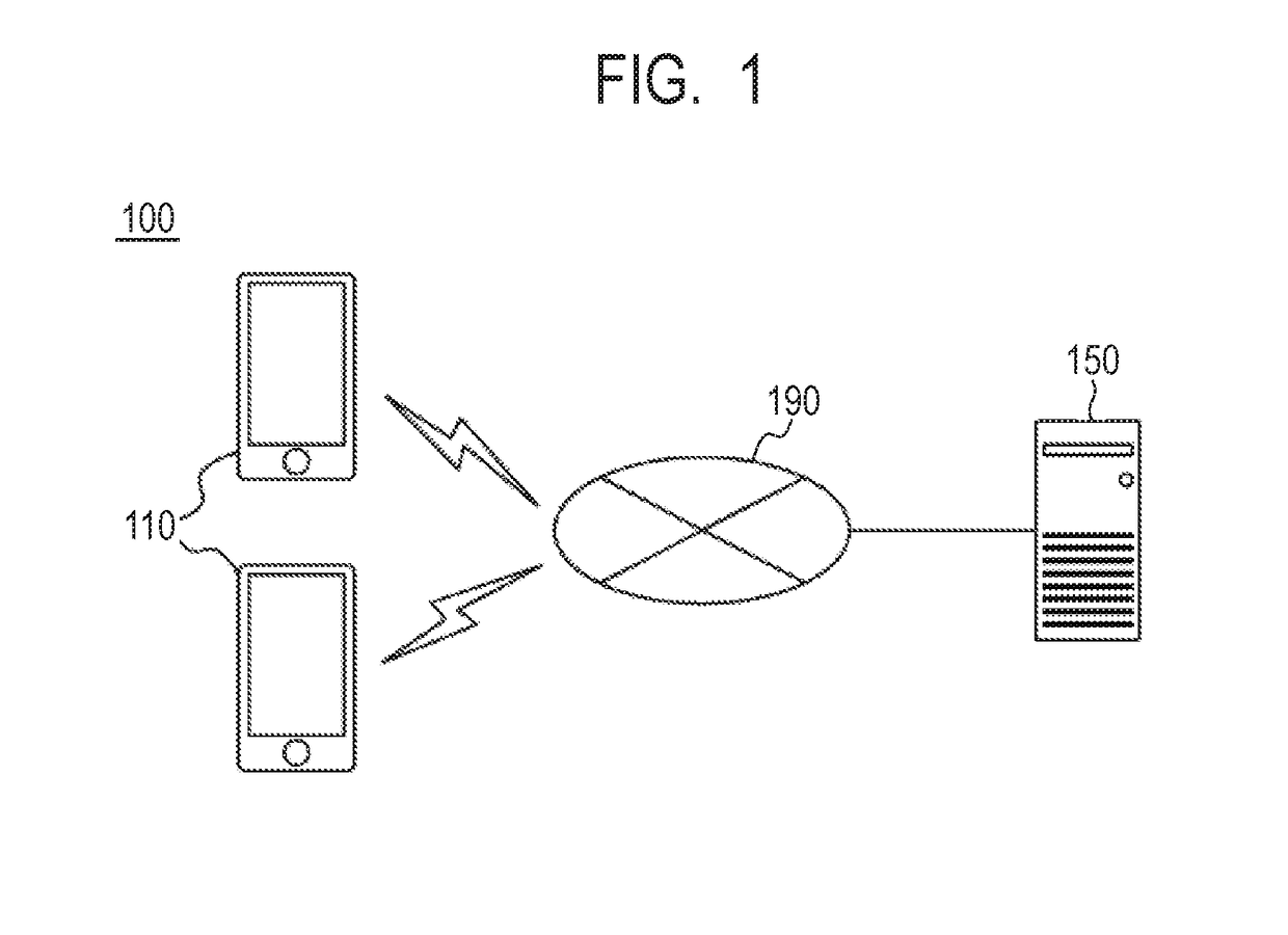
[0031]FIG. 1 is a schematic diagram of an image display system 100 according to the present example embodiment. The image display system 100 has a mobile terminal 110 and a server 150. The mobile terminal 110 and the server 150 are connected to each other via wired connection or wireless connection via a network 190 such as the Internet. The image display system 100 may include devices such as another server, another mobile terminal, or the like. The mobile terminal 110 is a terminal that is carried by a customer and has an image capture function using a camera and a function of displaying an image acquired from the server 150. The server 150 is a server that is installed at any location and performs storage and acquisition of an image.
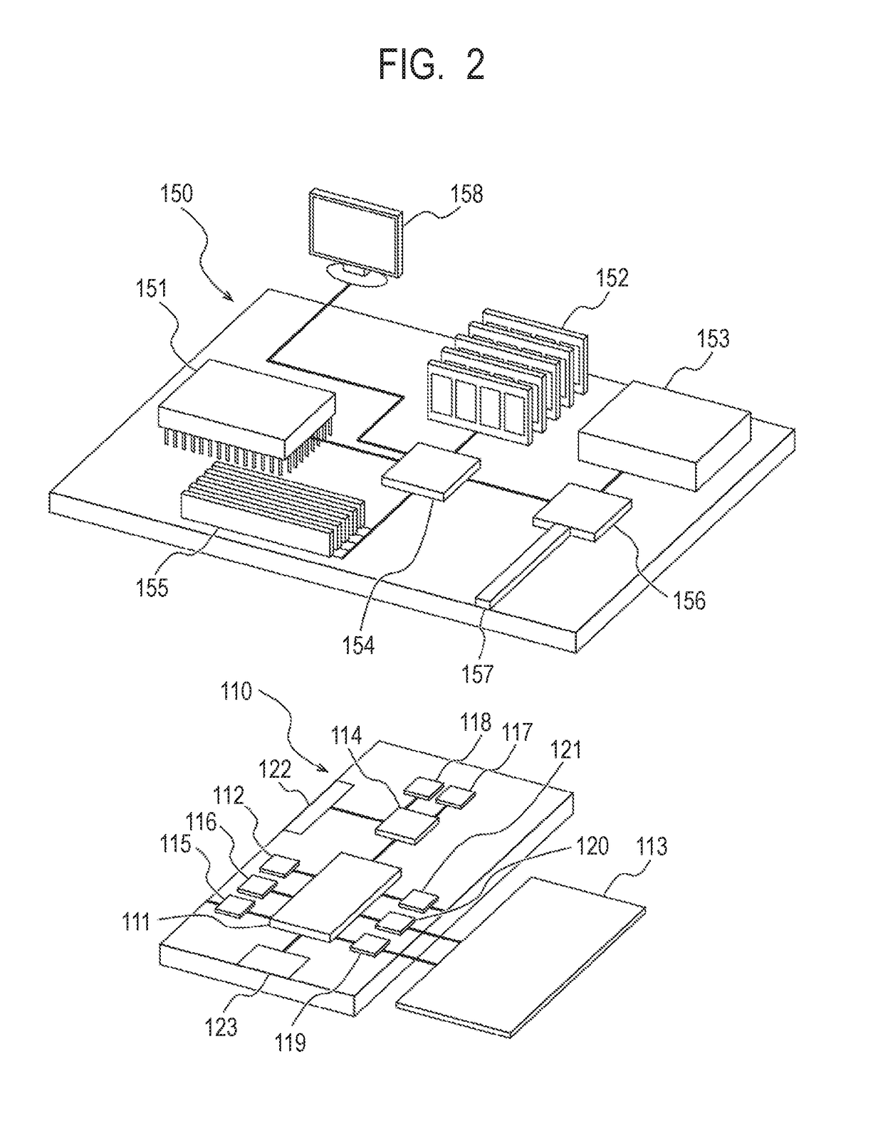
[0032]FIG. 2 is a general configuration diagram of the mobile terminal 110 and the server 150 according to the present example embodiment. Note that each of the mobile terminal 110 and the server 150 may be formed of a single device, or may be formed ...
second example embodiment
[0088]The present example embodiment provides a method for more accurately displaying a past image corresponding to the current captured range of the camera 115, that is, the user's field of view. The configuration of the image display system 100 according to the present example embodiment is the same as that of the first example embodiment, and the only difference is in a calculation method of a similarity degree. FIG. 9 is a schematic diagram illustrating positions and orientations of a current image and a past image. In FIG. 9, the positions and orientations of the current image and the past image are represented by arrows on an x-y plane with any point being the origin. The position of an arrow illustrates the position of the current image or the past image, the direction of an arrow illustrates the orientation of the current image or the past image. The positive direction in the y-axis is here defined as the north direction.
[0089]The orientation of the current image D1 is the n...
third example embodiment
[0092]The present example embodiment provides a method for more accurately displaying a past image corresponding to a current captured range of the camera 115, that is, the user's field of view. The configuration of the image display system 100 according to the present example embodiment is the same as that of the first example embodiment, and the only difference is in a calculation method of a similarity degree. FIG. 10 is a schematic diagram illustrating positions and orientations of a current image and a past image. In FIG. 10, the positions and orientations of the current image and the past image are represented by arrows on an x-y plane with any point being the origin, respectively. The position of an arrow illustrates the position of the current image or the past image, the direction of an arrow illustrates the orientation of the current image or the past image. The positive direction in the y-axis is here defined as the north direction.
[0093]The orientation of all the current...
PUM
 Abstract
Description
Claims
Application Information
 - R&D
- Intellectual Property
- Life Sciences
- Materials
- Tech Scout
- Unparalleled Data Quality
- Higher Quality Content
- 60% Fewer Hallucinations
Browse by: Latest US Patents, China's latest patents, Technical Efficacy Thesaurus, Application Domain, Technology Topic, Popular Technical Reports.
© 2025 PatSnap. All rights reserved.Legal|Privacy policy|Modern Slavery Act Transparency Statement|Sitemap|About US| Contact US: help@patsnap.com


