Method and device for representing an object

a technology of object representation and object image, applied in the field of object imaging process, can solve the problems of otf region in the axial direction, difficult process realization, and special adjustment difficulty

Inactive Publication Date: 2005-06-21
MAX PLANCK GESELLSCHAFT ZUR FOERDERUNG DER WISSENSCHAFTEN EV
View PDF23 Cites 188 Cited by
  • Summary
  • Abstract
  • Description
  • Claims
  • Application Information

AI Technical Summary

Benefits of technology

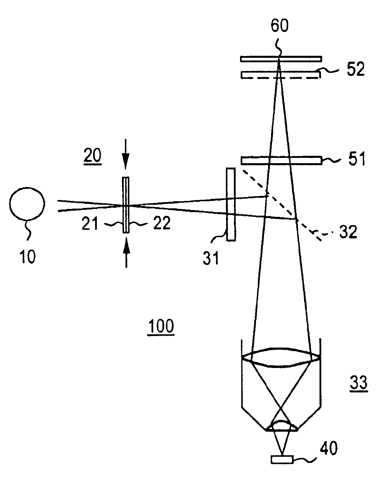
[0012]The basic idea of the invention is, for obtaining an object image (image of an object structure), to record at least two partial images of an object under different object conditions, which are implemented on the object with spatial patterns, with a non-linear function of the light detectable from the object point on the object conditions given at the object point existing for each object point and the partial images containing different contributions of various spatial frequency components of the object structure, and to obtain the desired object image from the partial images through reconstruction of the spatial frequency components. Achievi

Problems solved by technology

Thus, particularly in the 4Pi, I5M, and theta microscopes, the adjustment is especially difficult.
In addition, the processes are difficult to realize because they can be integrated in existing microscopic systems at great expense only.
In the wave field microscope, it is a significant problem that the OTF has regions in the axial direction in which it vanishes.
In addition, the wave field microscope and/or the 4Pi microscope do not provide any increase in resolution in the lateral direction in comparison with typical epifluorescence microscopy and/or confocal fluorescence microscopy.
This is time-consuming and problematic, above all in the imaging of time-dependent procedures.
Scanning processes require very f

Method used


Image

  • Method and device for representing an object
  • Method and device for representing an object
  • Method and device for representing an object

Examples


Embodiment Construction

[0033]The invention is first described in the following with reference to the theoretical foundations and then explained with reference to various examples. The invention is not restricted to the exemplary embodiments given. Altered embodiments under correspondingly varied object conditions can be realized depending on the application, particularly within the framework of the following statement of the concept.

[0034]The object or sections of the object to be detected during optical imaging are generally referred to in the following as “object”. Objects are, in particular, all types of biological or synthetic samples which are examined with typical imaging processes and localized resolution analysis processes, particularly microscopy and spectroscopy processes. Applications result, for example, in biology, medicine, chemistry, semiconductor technology, single molecule spectroscopy, and similar fields. The object can be solid, liquid, or gaseous.

[0035]“Object conditions” are generally...


PUM


Abstract

A process for obtaining an object image of at least one object (40) is described, wherein at least two partial images of the object (40) are taken under differing object conditions which are formed on the object with spatial patterns, wherein a non-linear dependence of the light detectable from the object point on the object conditions given at the object point exists and the partial images contain different contributions of various space frequency components of the object structure, and the desired object image is determined from the partial images by reconstruction of the space frequency components. Optical systems for implementing this type of process are also described.

Description

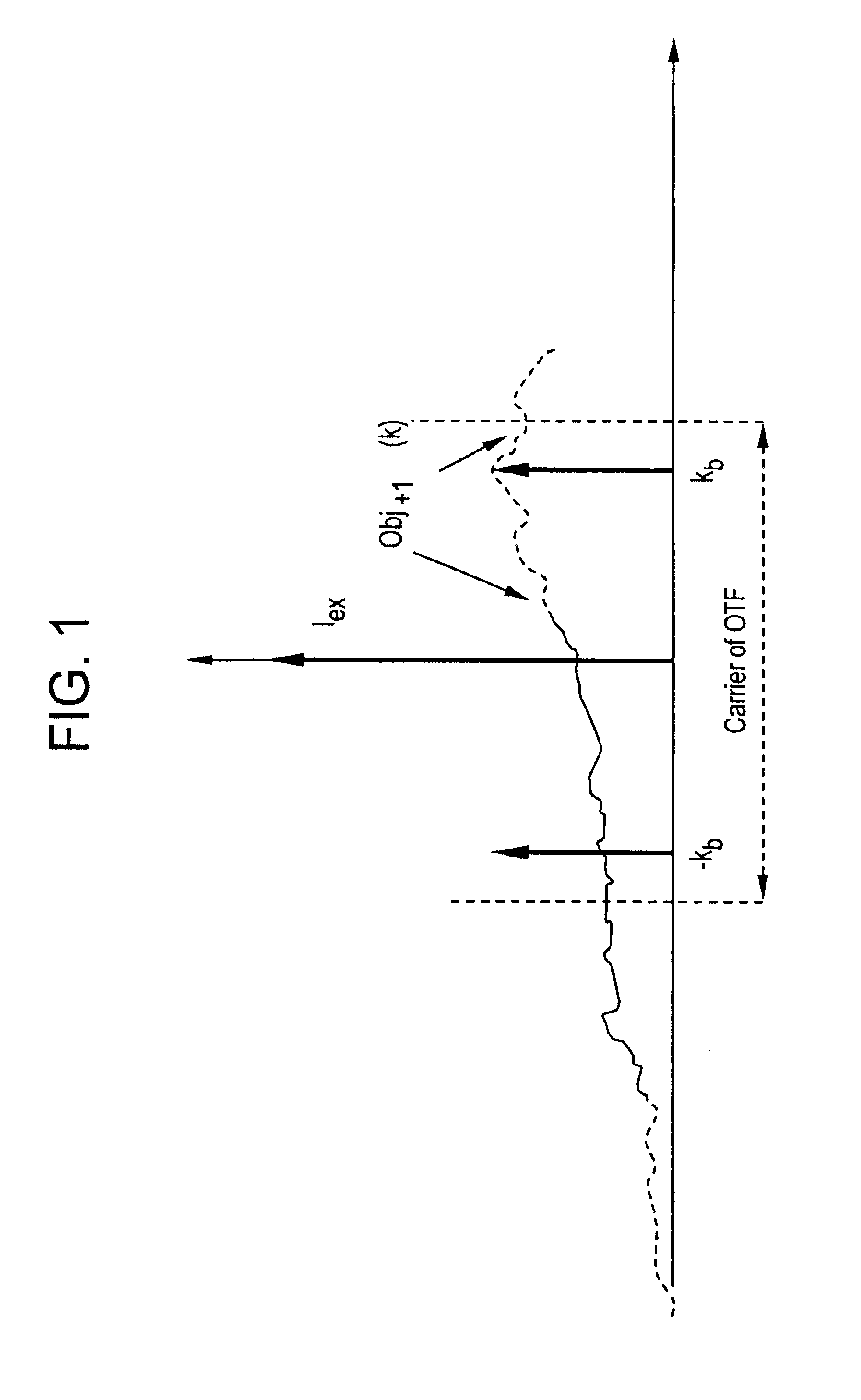
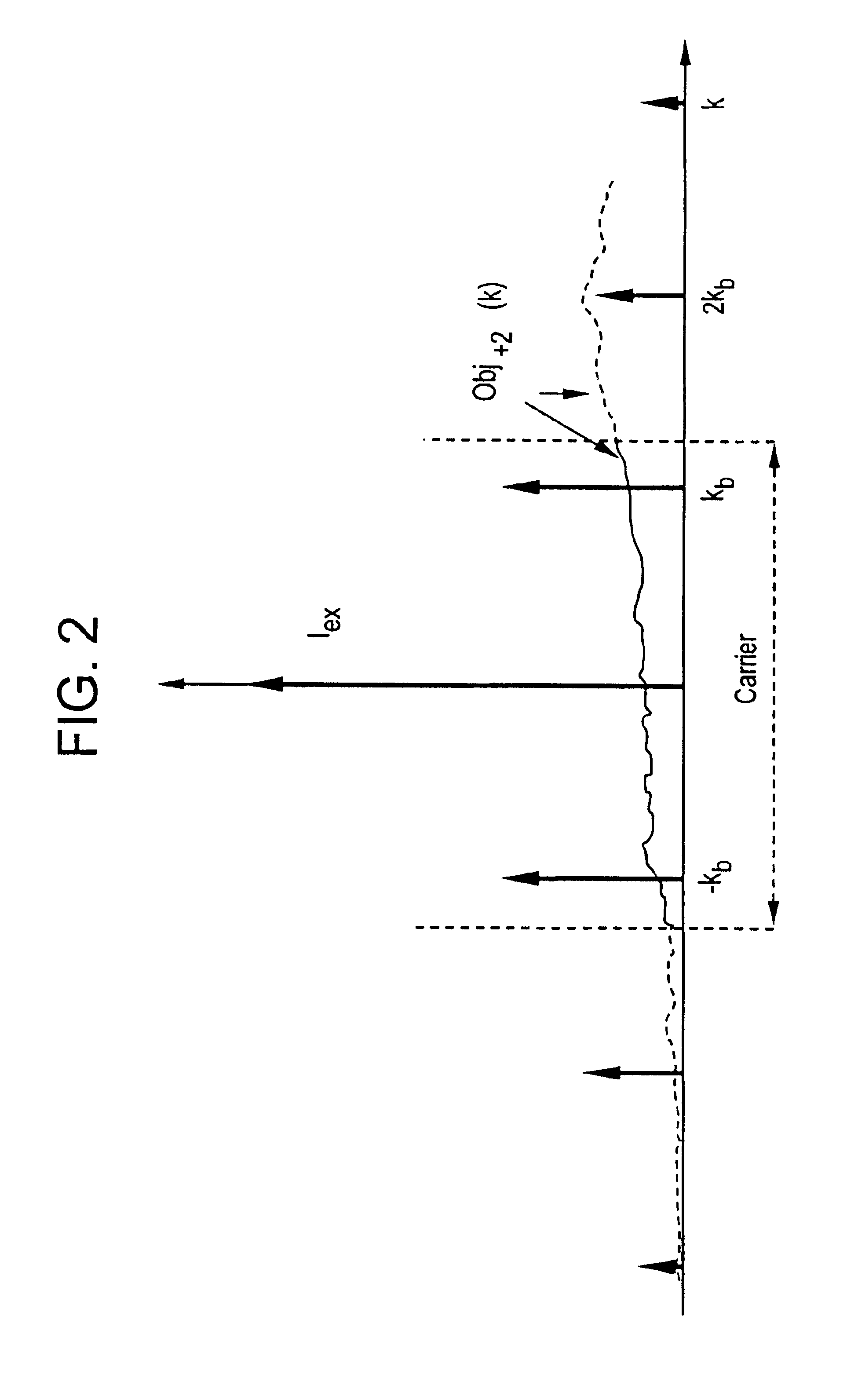
FIELD OF THE INVENTION[0001]The invention concerns a process for object imaging with high spatial resolution capability, particularly a light-optical microscope imaging process, and devices for performing this type of process.BACKGROUND[0002]The resolution capability of optical imaging systems is often decisively determined by the object-side aperture of an objective lens and its index of refraction. Light going out from an object can only be detected if it hits the objective within the acceptance angle of the objective. The higher the resolution capability is, the higher the spatial frequencies of the object structure to be imaged which can be detected. The detection of the spatial frequencies is described by the light-optical transfer function or modulation transfer function (in the following: OTF) of the optical systems. The OTF indicates which spatial frequencies, from which the object can be constructed by means of Fourier transformation, are retained in the optical imaging, an...

Claims


Application Information

Patent Timeline
IPC IPC(8): G02B21/00G02B27/46G02B21/36G01N21/17G01N21/62G06T7/00
CPCG02B21/00G02B27/46G02B21/367
Inventor HEINTZMANN, RAINERCREMER, CHRISTOPH
Owner MAX PLANCK GESELLSCHAFT ZUR FOERDERUNG DER WISSENSCHAFTEN EV
Why Eureka
Try Eureka