Synchronizing apparatus, synchronizing method, synchronizing program and data reproduction apparatus

Inactive Publication Date: 2007-04-26
SONY CORP
View PDF4 Cites 25 Cited by
  • Summary
  • Abstract
  • Description
  • Claims
  • Application Information

AI Technical Summary

Benefits of technology

[0017] That allows detecting the frequency error precisely. In addition, adjusting the loop filter of the PLL circuit based on the frequency error directly corrects the frequency error. In effect, that increases the accuracy of reproducing data.
[0018] In this manner, the synchronizing apparatus, the synchronizing method and the synchronizing program can detect the frequency error precisely. In addition, adjusting the loop filter of the PLL circuit based on the frequency error directly corrects the frequency error. Thus, the synchronizing apparatus, t

Problems solved by technology

In recent years, even though the optical disc device can record and read data from the optical disc at high speed, the speed of the PLL circuit is limited.
Therefore, the PLL circuit may include a pipeline delay.
In this case, in the optical disc device, the pipeline delay causes delay in a loop of the PLL circuit (i.e. loop delay).
The long time delay may cause not only phase errors but also freque

Method used


Image

  • Synchronizing apparatus, synchronizing method, synchronizing program and data reproduction apparatus
  • Synchronizing apparatus, synchronizing method, synchronizing program and data reproduction apparatus
  • Synchronizing apparatus, synchronizing method, synchronizing program and data reproduction apparatus

Examples


Embodiment Construction

[0038] An embodiment of the present invention will be described in detail with reference to the accompanying drawings.

(1) Configuration of Optical Disc Device

(1-1) Overall Configuration of Optical Disc Device

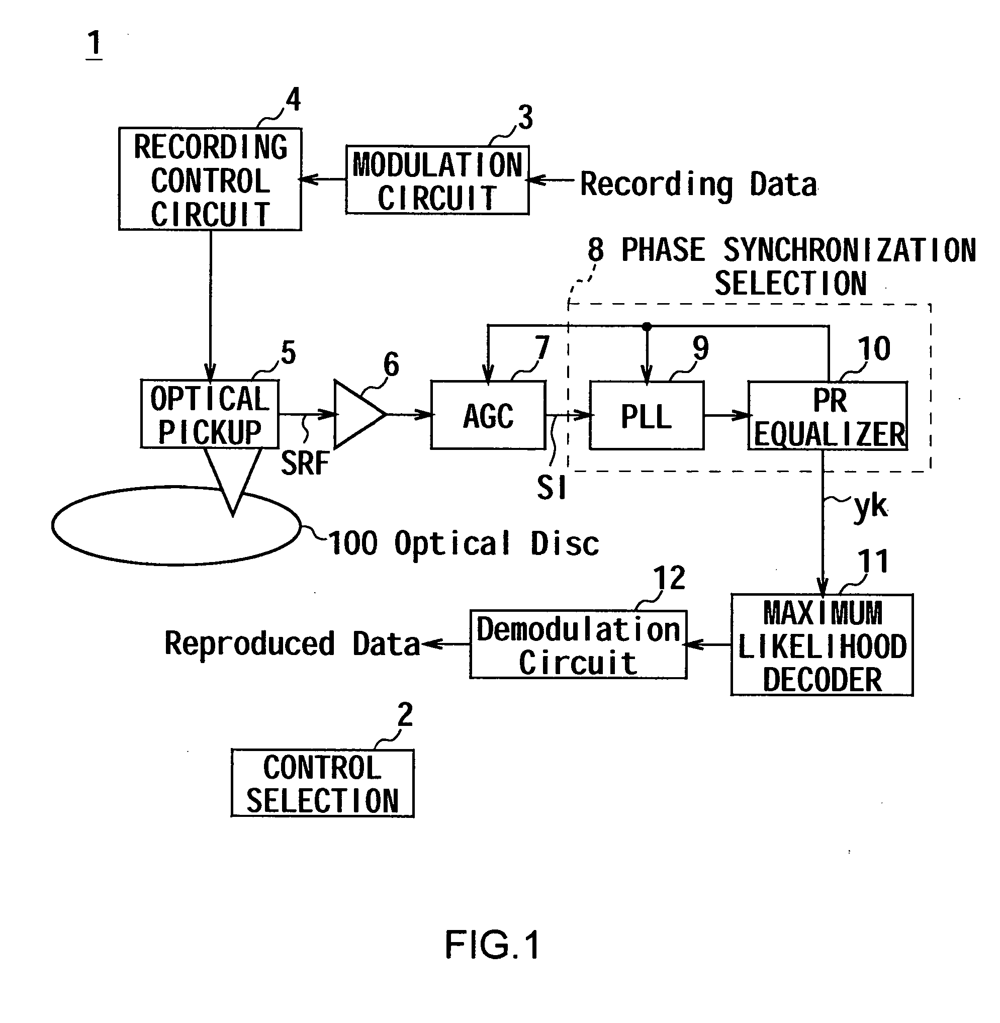
[0039]FIG. 1 shows an optical disc device 1 having a control section 2 that takes overall control of the optical disc device 1. In general, the optical disc device 1 records, in accordance with recording data, data strings on an optical disc 100 with the format of “Blu-ray Disc ™”. The optical disc device 1 also reads out the data strings from the optical disc 100 to generate reproduced data.

[0040] The control section 2 includes a Central Processing Unit (CPU) (not shown), which is a major component; a Read Only Memory (ROM) (not shown); and a Random Access Memory (RAM) (not shown). The control section 2 reads out various programs, such as a control program, from the ROM and loads them onto the RAM to perform process such as recording and reproducing data from the optical d...


PUM


Abstract

A synchronizing apparatus, which controls, by a PLL circuit, a sampling clock to be used to sample input data and synchronizes a phase of the sampling clock with a target phase that is desirable for sampling the input data, includes: phase error detection means for detecting a phase error from sampling data and the sampling clock, the sampling data being sampled from the input data at timing of the sampling clock; frequency error detection means for detecting, based on a differential coefficient obtained as a result of detecting the phase error, a frequency error; and frequency correction means for correcting a frequency of the sampling clock such that the detected frequency error becomes close to zero by adding a frequency correction value to an integral term of a loop filter of the PLL circuit, the frequency correction value being calculated based on the frequency error.

Description

CROSS REFERENCE TO RELATED APPLICATION [0001] The present invention contains subject matter related to Japanese Patent Application JP2005-310077 filed in the Japanese Patent Office on Oct. 25, 2005, the entire contents of which being incorporated herein by reference. BACKGROUND OF THE INVENTION [0002] 1. Field of the Invention [0003] The present invention relates to a synchronizing apparatus synchronizing method, synchronizing program and data reproduction apparatus, and is preferably applied to an optical disc device, for example. [0004] 2. Description of Related Art [0005] Typically, an optical disc device records data on an optical disc and reads out the data from the optical disc to reproduce in accordance with standards such as “Blu-ray Disc (Registered Trademark)” and Digital Versatile Disc (DVD). This kind of optical disc device is here to stay. [0006] To read data from the optical disc, the optical disc device for example emits a laser beam to the optical disc, generates rep...

Claims


Application Information

Patent Timeline
IPC IPC(8): H03D3/24
CPCH04L7/0331G11B20/1024H04L7/0029H04L7/042H04L7/10
Inventor HIGASHINO, SATORU
Owner SONY CORP
Why Eureka
Try Eureka