On-machine inspection indicator setup block

a technology of indicator and setup block, which is applied in the direction of mechanical measuring arrangement, manufacturing tools, instruments, etc., can solve the problems of introducing human error during routine use, machinists using micrometers to qualify the outside periphery of parts, and work pieces may have too large a size to accurately measure with a micrometer, so as to achieve the effect of not distorting the flatness of the devi

Active Publication Date: 2021-06-22
LAUSE SHAWN THOMAS
View PDF7 Cites 3 Cited by
  • Summary
  • Abstract
  • Description
  • Claims
  • Application Information

AI Technical Summary

Benefits of technology

[0008]The invention is a mechanical device used to align a test indicator from a spindle centerline to transfer a measurement for accurately measuring surfaces on a machine tool. The device locates on any planar surface on a machine tool with a magnetic attraction to prevent the device from moving. Magnetic inserts recessed on the bottom of the device provide this magnetic attraction without distorting the device's flatness. The precision bore located in the center of the device provides a radial measurement for a test indicator. The precision bore has a nominal size as the bore's radius becomes the mathematical value for calculating measurements. This radial measurement cooperates with a digital readout of the machine tool to position a work piece a certain radial distance from a surface. The undercuts on the two sides of the device allow for hand removal without scratching and damaging an underlying surface.

Problems solved by technology

Hand tools, such as micrometers and calipers, have regular use by machinists however that introduces human error during routine usage.
Machinists use micrometers to qualify the outside periphery of parts however at less accuracy than test indicators.
Work pieces may have too large a size to accurately measure with a micrometer due to micrometer weight, availability, and the design of the profile.
Flatness verification works very well; however, it does not provide actual measurements.
The machine specific hardware and software required to operate tool probes limits their efficiency because they required well trained, skilled operators.
Because of machine specific design hardware and software, tool probes have become too costly to use on all machine tools.

Method used


Image

  • On-machine inspection indicator setup block
  • On-machine inspection indicator setup block
  • On-machine inspection indicator setup block

Examples


Embodiment Construction

[0056]The foregoing features, object, and advantages of the invention will become apparent to those skilled in the trade from the following detailed description of the preferred embodiment, especially when considered in conjunction with the accompanying drawings.

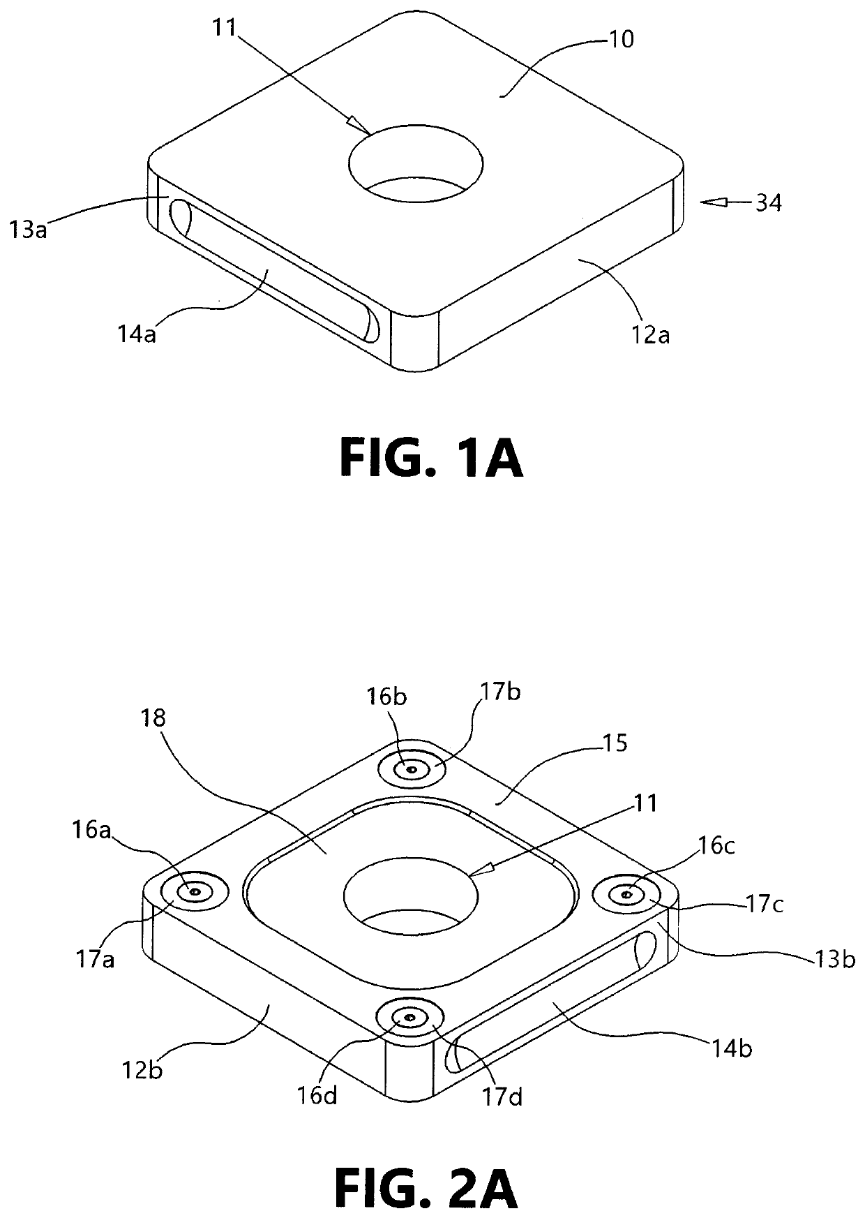
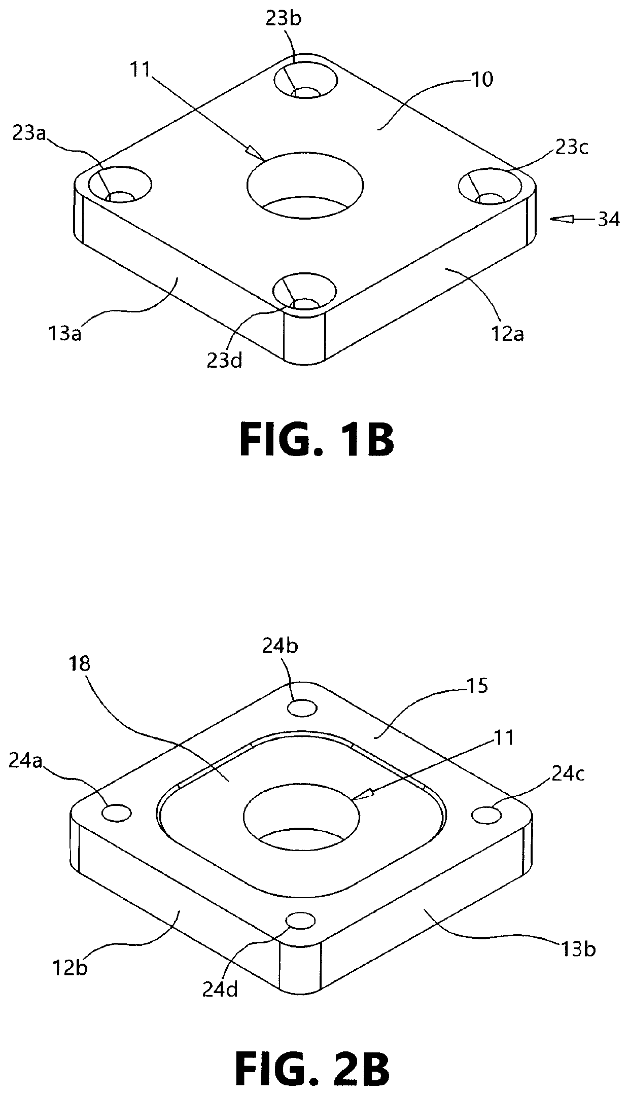
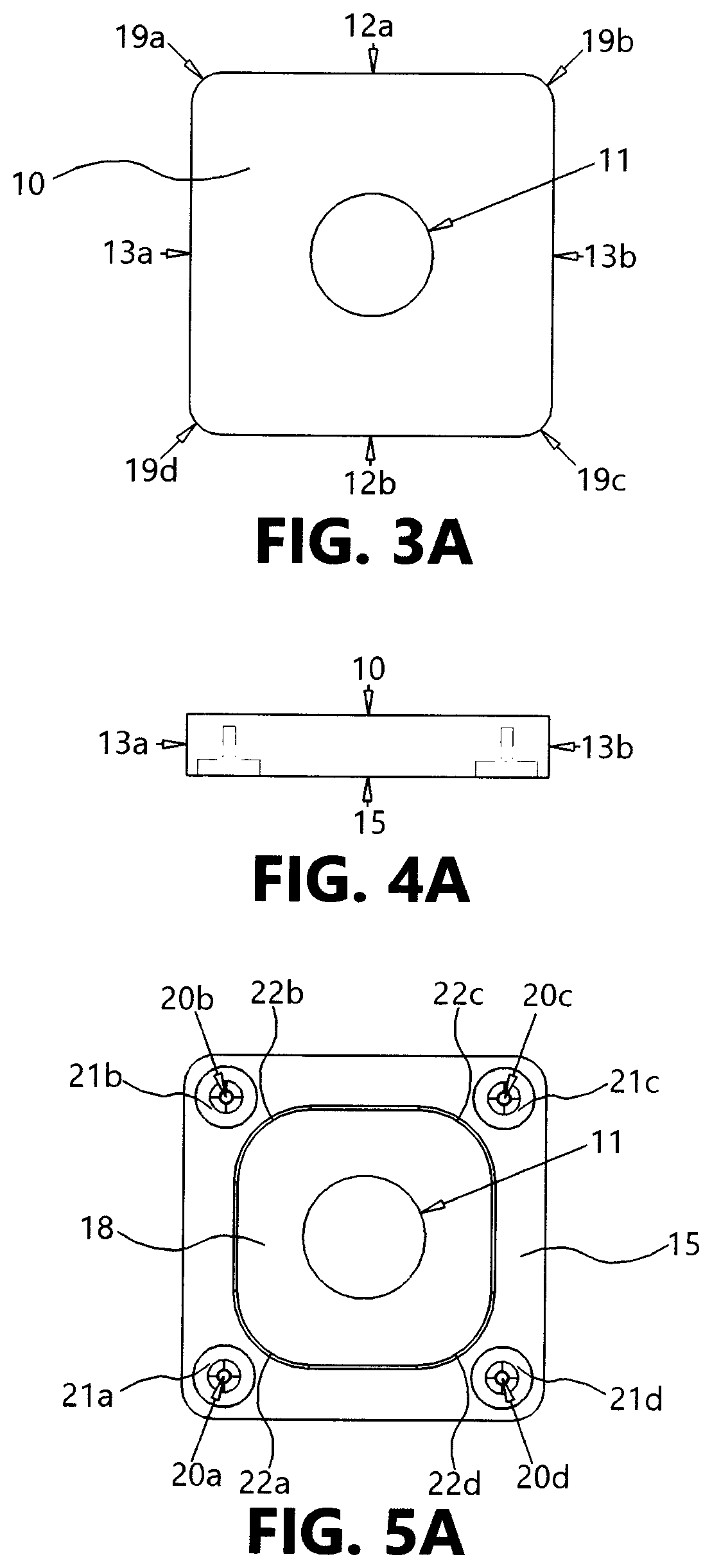
[0057]The present invention, On-Machine Inspection Indicator Setup Block, provides a repeatable way of measuring work piece surfaces on machine tools.

[0058]FIG. 1A shows a top perspective view of the alternate embodiment of the present invention 34. The invention has a body here shown in isometric as a prismatic square with rounded corners. The device has a top surface 10 shown with a precision bore 11 located in the center. The precision bore 11, centered on the device, has a nominal size that communicates through the entire device. The precision bore 11 has a circularity less than 0.0001 in (one ten-thousandths of an inch) of total indicator readout. Rotating a test indicator from the precision bore's centerline at a compl...


PUM


Abstract

The invention of a device has four threaded bolts that engage cooperatively threaded apertures in a base. These thread bolts hold the device in a temporary yet stationary position. The device has non-magnetic metal which allows test indicators to display accurate results free from any magnetic fields. The device has a precision bore of a nominal size. The radial value of the nominal size precision bore provides for mathematical calculation of the spindle centerline to work piece distance for measuring. The device has undercuts on both of its sides to aid in removing by hand. These undercuts allow the device to pivot from its stationary position for removal without damaging the planar surface. Alternatively, the device has four magnetic inserts, pocketed upwardly from the bottom surface.

Description

CROSS-REFERENCE TO RELATED APPLICATION[0001]This non-provisional application claims priority to pending provisional application No. 62 / 674,712 filed on May 22, 2018 which is owned by the same inventor.FIELD OF THE INVENTION[0002]The present invention relates to a precision machined internal diameter gage. The device is used to precisely setup a test indicator on a machine tool spindle. The device determines the precise diameters of cutting toolsBACKGROUND OF THE INVENTION[0003]The manufacturing of work pieces with machine tools offers precisions repeatable results. To qualify these results, operators must use hand tools and other precision instruments to inspect work pieces before, during, and after machining processes. Hand tools, such as micrometers and calipers, have regular use by machinists however that introduces human error during routine usage.[0004]In the die / mold industry, many work pieces have mating features which require high tolerance dimensions. The outside periphery ...

Claims


Application Information

Patent Timeline
Patent Type & Authority Patents(United States)
IPC IPC(8): G01B5/25B23Q17/22G01B5/12
CPCB23Q17/225B23Q2717/00G01B5/12B23Q17/2233G01B5/008G01B21/042
Inventor LAUSE, SHAWN THOMAS
Owner LAUSE SHAWN THOMAS
Why Eureka
Try Eureka