Steering assist system

a technology of steering assist and steering force, which is applied in the direction of power steering, fluid steering, vehicle components, etc., can solve the problems of unfavorable driver's adds limitations as to the overall structure of the assist system, and suffers from an influence of a change, etc., to achieve smooth assist switching and simple manner

Active Publication Date: 2021-08-24
TOYOTA JIDOSHA KK
View PDF7 Cites 0 Cited by
  • Summary
  • Abstract
  • Description
  • Claims
  • Application Information

AI Technical Summary

Benefits of technology

[0006]In the case where the vehicle is being steered, the steering assist system constructed as described above avoids the assist force from being abruptly generated by the first assist portion when the engine operates after the assist force by the second assist portion becomes zero. Thus, the steering system prevents or reduces a change in the assist force with respect to the steering operation by the driver. That is, the steering assist system enables proper switching from the assist force by the second assist portion to the assist force by the first assist portion.
[0014]This form aims at addressing the problem described above. According to this form, when there occurs a failure in which the second assist portion does not work during running of the vehicle in the EV mode, the steering assist system executes the assist switching from the assist by the second assist portion to the assist by the first assist portion. In the assist switching, the assist force by the first assist portion is gradually increased in the case where the steering operation is being performed. According to this form, the assist force is gradually made larger when the assist force that has once become lost again generated, thus enabling the driver to easily maintain an appropriate steering amount.
[0016]Although the magnitude of the set assist force in this form is not limited, the set assist force may have the same magnitude as the assist force generated before the second portion fails to operate, for instance. Owing to this set assist force, the assist force by the first assist portion is gradually increased after the occurrence of the failure of the second assist portion up to the assist force whose magnitude is equal to that of the assist force that has been generated by the second assist portion before the occurrence of the failure, thus preventing a change in the operation feeling felt by the driver in the steering operation before and after the occurrence of the failure of the second assist portion. It is desirable that the assist force by the first assist portion be gradually increased such that the assist force reaches the set assist force within about 0.5-5 seconds.
[0021]This form enjoys the advantage that the operation feeling felt by the driver in the steering operation does not change before and after the occurrence of the failure of the second assist portion.
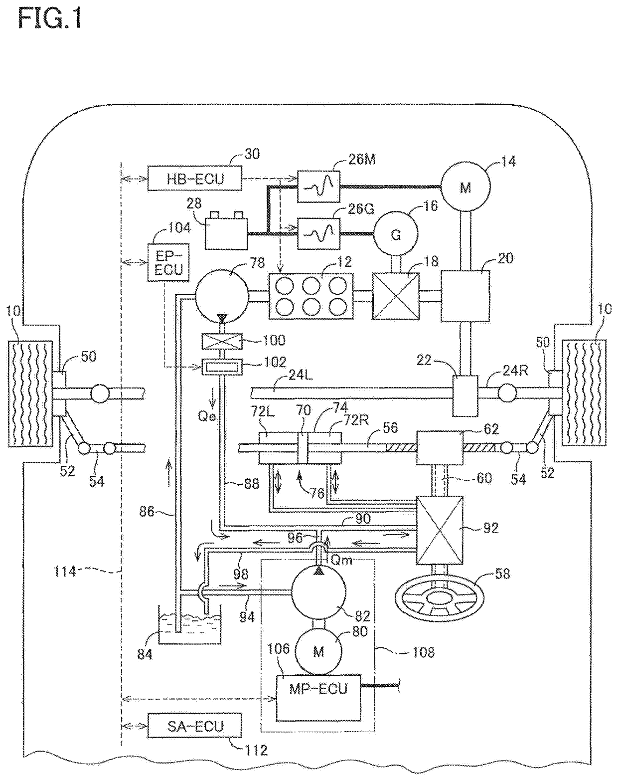
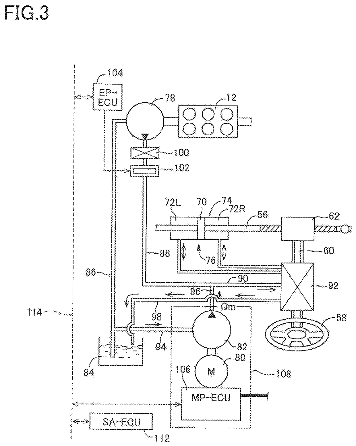
[0033]The engine-pump ejection flow rate controller according to this form may employ an electromagnetic valve mechanism having a known ordinary structure as illustrated in FIG. 2 of the Japanese Patent Application Publication No. 2014-19290, for instance. The engine-pump ejection flow rate controller is configured to control an electric current supplied to a solenoid so as to permit the working fluid to pass therethrough at a flow rate in accordance with the controlled electric current. Owing to provision of the engine-pump ejection flow rate controller, this form offers an advantage of preventing a rapid change in the flow rate of the working fluid ejected to the assist device when the running mode of the vehicle is switched from the EV mode to a mode in which the vehicle runs by driving of the engine (hereinafter referred to as “engine mode” where appropriate) or to a mode in which the vehicle runs by driving of both of the drive motor and the engine (hereinafter referred to as “hybrid mode” where appropriate). Further, in the engine mode and the hybrid mode, the engine-pump ejection flow rate controller may control the engine pump to eject the working fluid at the engine-pump ejection flow rate lower than the required receiving flow rate, and an insufficient flow rate, which is a shortage in the required receiving flow rate and which cannot be covered by the engine-pump ejection flow rate, may be covered by the motor-pump ejection flow rate. The thus configured assist system ensures sufficient assist capability while achieving downsizing of the engine pump. The motor-pump ejection flow rate controller in this form may be constituted as an electronic controller including a computer and drive circuits for the electric motor.
[0035]In this form, the gradient at which the assist force is gradually increased in the assist switching is made constant. This form enables relatively smooth assist switching in a relatively simple manner.

Problems solved by technology

In the case where the assist switching is not properly executed, however, it is expected that the driver will suffer from an influence of a change in the assist force via the steering operation member.
In this case, it is expected that the driver undesirably suffers from an influence of the change in the assist force.
This form adds limitation as to the overall structure of the assist system and relates to what is called two-pump hydraulic steering assist system.
In this form, the failure of the second assist portion means a failure that renders the motor pump inoperative.
Specifically, the failure of the second assist portion includes a failure of the motor pump itself and a failure of the electric motor that drives the motor pump, for instance.

Method used


Image

  • Steering assist system
  • Steering assist system
  • Steering assist system

Examples


Embodiment Construction

[0044]A steering assist system according to one embodiment of the present disclosure will now be explained in detail with, reference to the drawings. It is to be understood that the disclosure is not limited to the details of the following embodiment but may be changed and modified based on the knowledge of those skilled in the art.

[A] Structure of Vehicle on Which Steering Assist System is Installed

[0045]As shown in FIG. 1, a vehicle on which a steering assist system according to the present embodiment is installed has four wheels 10, namely, front right and left wheels and rear right and left wheels. In FIG. 1, the two rear wheels are not illustrated. The two front wheels 10 are drive wheels. The vehicle is a hybrid vehicle whose front wheels 10 can be driven by both of an engine 12 and a drive motor 14 as an electric motor. The front wheels 10 are steerable wheels. In the following description, the steering assist system will be simply referred to as “assist system” where appropr...


PUM


Abstract

A steering assist system for a hybrid vehicle capable of being driven by both of an engine and a drive motor, including a first assist portion and a second assist portion configured to assist a steering force respectively utilizing the engine and an electric motor each as a drive source, wherein the steering force is assisted only by the second assist portion in a motor-driven state in which the vehicle is driven only by the drive motor, and wherein the steering assist system is configured to, upon occurrence of a failure of the second assist portion in the motor-driven state, drive the engine, execute assist switching from an assist by the second assist portion to an assist by the first assist portion, and gradually increase, in the assist switching, an assist force by the first assist portion up to a set assist force when the vehicle is being steered.

Description

CROSS REFERENCE TO RELATED APPLICATION[0001]The present application claims priority from Japanese Patent Application No. 2018-022646, which was filed on Feb. 12, 2018, the disclosure of which is herein incorporated by reference in its entirety.BACKGROUNDTechnical Field[0002]The following disclosure relates to a steering assist system configured to be installed on a vehicle and to assist steering of wheels of the vehicle.Description of Related Art[0003]Hybrid vehicles configured to be capable of being driven by both of an engine and a drive motor have recently become popular, and there has been proposed a steering assist system for assisting a steering force generated by an operation of a steering operation member performed by a driver, as disclosed in Japanese Patent Application Publication No. 2014-19290, for instance. The disclosed system includes a first assist portion configured to assist the steering force utilizing the engine as a drive source and a second assist portion confi...

Claims


Application Information

Patent Timeline
Patent Type & Authority Patents(United States)
IPC IPC(8): B62D5/06B62D5/065B62D5/09B62D5/18B62D5/10B62D5/20
CPCB62D5/064B62D5/065B62D5/09B62D5/10B62D5/18B62D5/20B62D5/063
Inventor NISHIDA, TAKESHIFUJITA, SHUJI
Owner TOYOTA JIDOSHA KK
Why Eureka
Try Eureka