Quantum interference unit, quantum interference device, atomic oscillator, electronic apparatus, and moving object

a quantum interference and quantum interference technology, applied in the direction of pulse automatic control, oscillation generator, data conversion, etc., can solve the problems of frequency stability deterioration and increase power consumption, and achieve excellent reliability

Active Publication Date: 2016-05-17
MICROCHIP TECH INC
View PDF13 Cites 0 Cited by
  • Summary
  • Abstract
  • Description
  • Claims
  • Application Information

AI Technical Summary

Benefits of technology

[0008]An advantage of some aspects of the invention is to provide a quantum interference unit, a quantum interference device and an atomic oscillator in which power saving can be achieved and in which a change in characteristics caused by a magnetic field due to magnetization of the package can be prevented or reduced. Another advantage of some other aspects of the invention is to provide an electronic apparatus and a moving object which have such a quantum interference device and are highly reliable.
[0013]According to this configuration, the magnetic field from the coil can be made to act on the metal atoms in the gas cell to improve characteristics. Here, since the package is non-magnetic, the magnetic field from the coil can be made to act on the metal atoms in the gas cell even though the coil is arranged on the outside of the package. Also, as the coil is arranged on the outside of the package, the volume within the package can be reduced and consequently miniaturization of the quantum interference unit can be achieved. Moreover, the reduction in the volume within the package enables enhancement of reliability when the inside of the package is vacuum-sealed.Application Example 3
[0041]According to this configuration, a moving object with excellent reliability can be provided.

Problems solved by technology

Therefore, the magnetic field acting on the alkali metal in the gas cell changes which causes a problem of frequency stability deterioration.
However, since the ceramic has a high radiation heat absorptance, a great amount of heat escapes to the outside from inside the package which causes a problem of increased power consumption.

Method used


Image

  • Quantum interference unit, quantum interference device, atomic oscillator, electronic apparatus, and moving object
  • Quantum interference unit, quantum interference device, atomic oscillator, electronic apparatus, and moving object
  • Quantum interference unit, quantum interference device, atomic oscillator, electronic apparatus, and moving object

Examples


Embodiment Construction

[0050]Hereinafter, a quantum interference unit, a quantum interference device, an atomic oscillator, an electronic apparatus and a moving object according to the invention will be described in detail, on the basis of an embodiment shown in the accompanying drawings.

1. Atomic Oscillator (Quantum Interference Device)

[0051]First, an atomic oscillator (quantum interference device) will be described. While an example in which a quantum interference device is applied to an atomic oscillator will be described below, the quantum interference device is not limited to this example and can be applied to, for example, a magnetic sensor, quantum memory or the like, as well as an atomic oscillator.

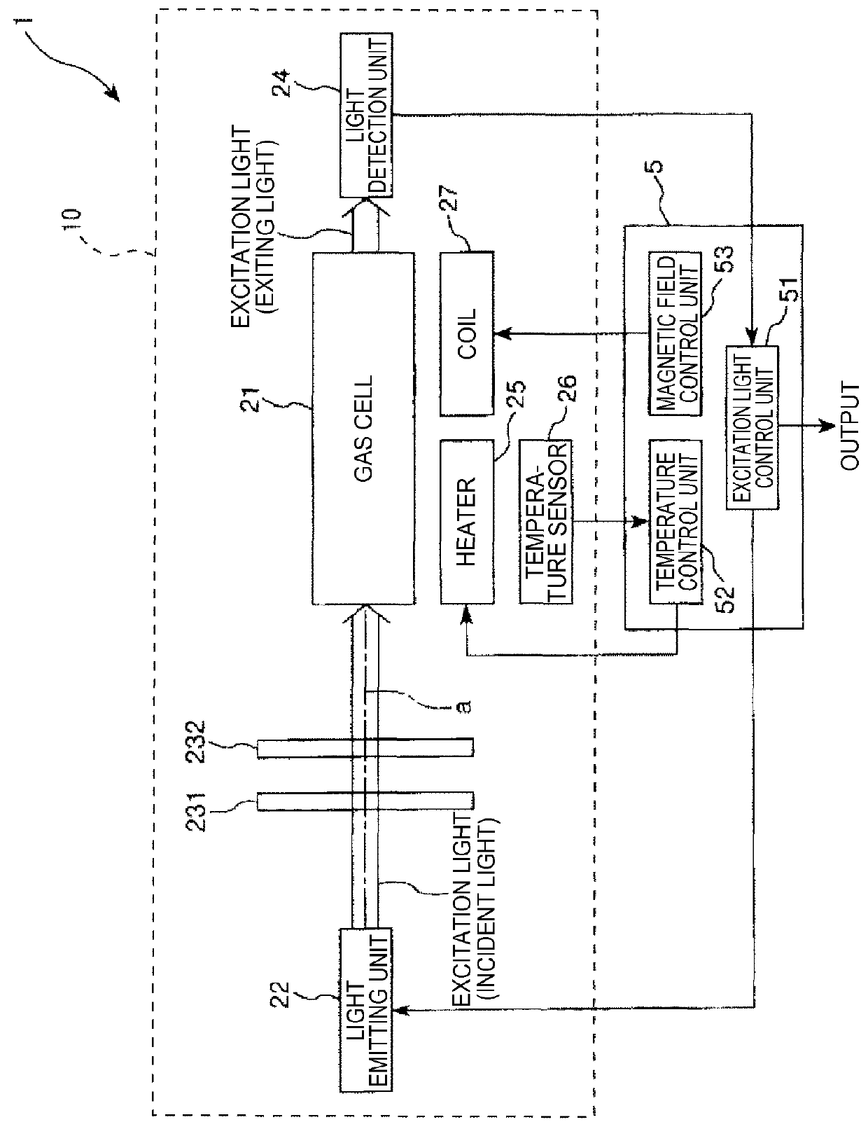
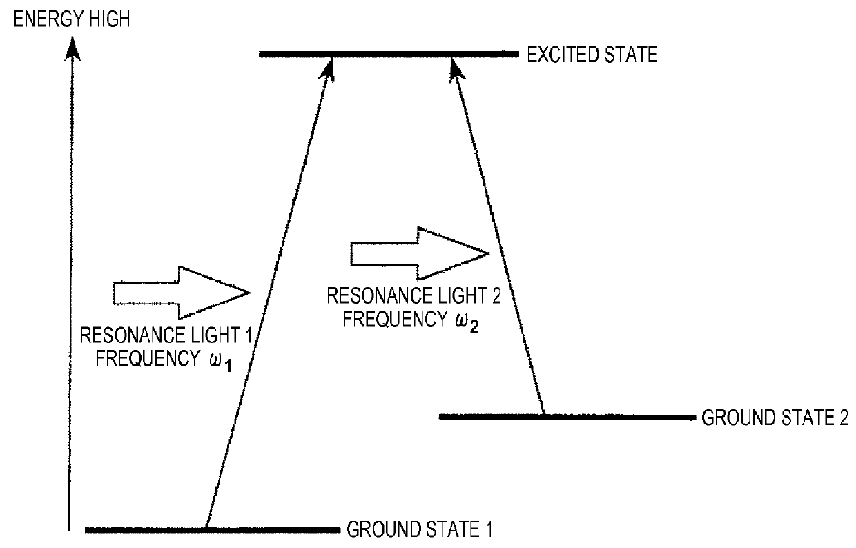
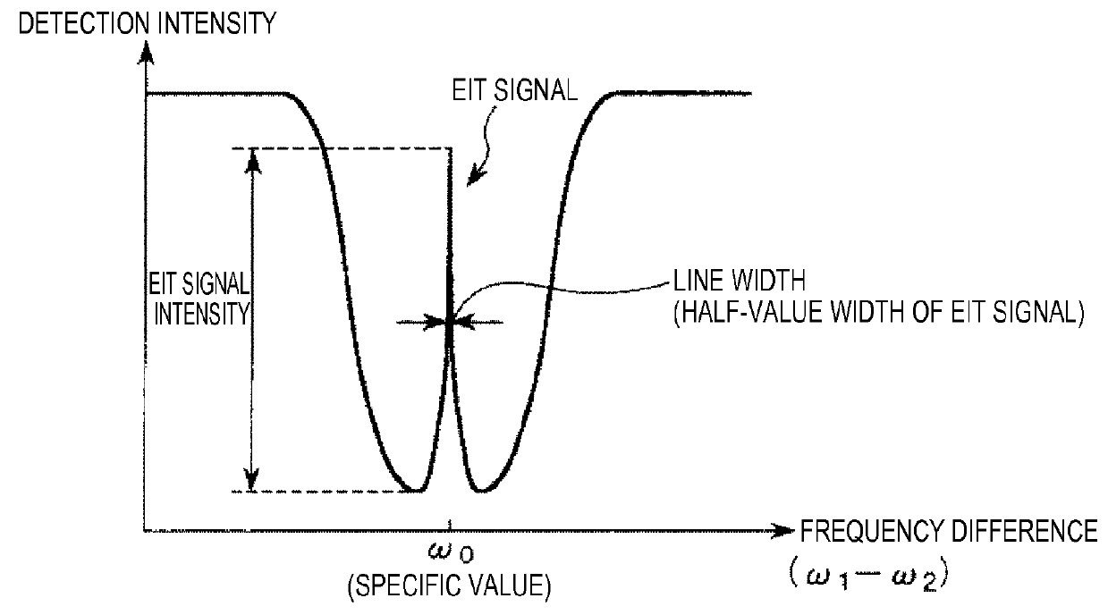
[0052]FIG. 1 is a schematic view showing an atomic oscillator (quantum interference device) according to an embodiment of the invention. FIG. 2 illustrates the energy states of an alkali metal. FIG. 3 is a graph showing the relation between the frequency difference between two lights from a light emitti...


PUM


Abstract

An atomic oscillator includes: a gas cell which houses metal atoms; a heater which adjusts a temperature of the gas cell; and a package which houses the gas cell and the heater. The package includes a non-magnetic metal layer.

Description

BACKGROUND[0001]1. Technical Field[0002]The present invention relates to a quantum interference unit, a quantum interference device, an atomic oscillator, an electronic apparatus, and a moving object.[0003]2. Related Art[0004]An atomic oscillator which oscillates on the basis of energy transition of atoms of an alkali metal such as rubidium or cesium is known. Generally, the operating principles of atomic oscillators are roughly divided into a system utilizing double resonance of light and microwaves and a system utilizing a quantum interference effect (CPT (coherence population trapping)) of two lights with different wavelengths.[0005]In an atomic oscillator of either system, an alkali metal is enclosed in a gas cell, and the gas cell needs to be heated to a predetermined temperature in order to maintain the alkali metal in a gaseous state. Also, in general, the gas cell is housed in an airtightly sealed package, and a coil for applying a steady magnetic field to the alkali metal i...

Claims


Application Information

Patent Timeline
Patent Type & Authority Patents(United States)
IPC IPC(8): H03B17/00G06F5/14H03L1/04H03L7/26H03B1/04
CPCG06F5/14H03B1/04H03B17/00H03L7/26G04F5/14
Inventor HASHI, YUKIHIRO
Owner MICROCHIP TECH INC
Why Eureka
Try Eureka