Gas/oil well monitoring system

a monitoring system and gas/oil well technology, applied in the field of data delivery to a user system, can solve the problems of difficult visits, inaccurate measurements, and frequent calibration of “gauges” and replacement of equipmen

Inactive Publication Date: 2005-11-22
OLEUMTECH CORP
View PDF11 Cites 244 Cited by
  • Summary
  • Abstract
  • Description
  • Claims
  • Application Information

AI Technical Summary

Benefits of technology

[0015]According to yet another embodiment, the monitoring unit and the relay unit are normally in a sleep mode, with only minimal circuitry active. Advantageously, the use of a sleep mode allows the monitoring unit and relay unit to conserve power allowing their batteries to last longer.

Problems solved by technology

The gas / oil well sites are typically located in remote areas, which are difficult to visit.
The measurements, however, can be inaccurate due to mechanical error (e.g., wear, sticking of parts, etc.), human error (e.g., misreadings) and other conditions (e.g., bad weather).
Exacerbating these problems, the “gauges” have to be calibrated often and replaced periodically due to malfunction or wear.
Moreover, there may be a significant delay in getting the information from the “gaugers” to the intended audience.
This delay can be grave if a malfunction or alarm triggering event occurs at the gas / oil well.
Thus, there is no process or mechanism by which alarm events—such as an over-spill in an oil tank—can be quickly determined.
Likewise, if there happens to be bad weather, such as a tropical storm, “gaugers” may likely not perform their gauging duties, thereby preventing the collection of much needed information.
Similarly, there is no process by which the end recipient of the information can verify whether or not the “gauger” actually took the measurement or the method which was used.
By way of example, a “gauger” could be inebriated or drugged while recording the measurement, and thus later report erroneous information.
In addition to these problems, the gas / oil well site itself is an extraordinarily dangerous place.
Moreover, the natural gas and oil present in the oil well area are extremely dangerous fire and explosion hazards.
Finally, since many of these gas / oil well sites are located in remote areas, often time venomous snakes and vicious alligators pose another safety hazard a “gauger” must confront.
Thus “gaugers” place themselves in much danger with every visit to the gas / oil well site.
Furthermore, the information that the “gaugers” gather may lack accuracy and precision.
Also, any information gathered may only reach its intended audience after hours if not days of delay.

Method used


Image

  • Gas/oil well monitoring system
  • Gas/oil well monitoring system
  • Gas/oil well monitoring system

Examples


examples

[0092]Generally, the originating device directs the message flow of communication. As described above, message flow may be originated by the monitoring unit, relay unit or host interface. Below are some examples of message flow of some embodiments of the invention.

Communications Between the Host Interface and Relay Unit

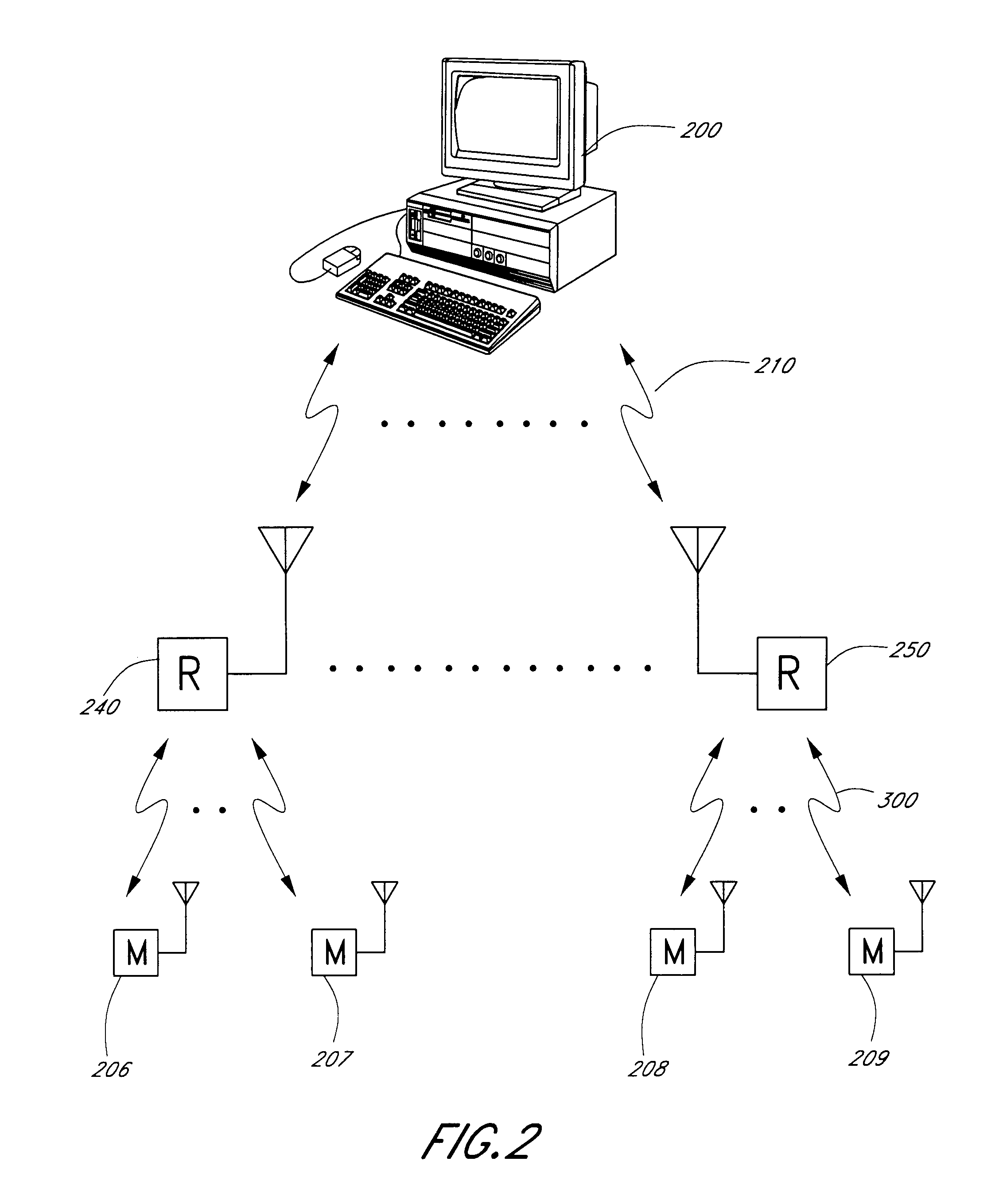
[0093]The host interface 200 can originate message flow by contacting the relay unit 240. The host interface 200 calls the cellular phone of the relay unit 240 or uses a communication medium, such as a landline. Although the relay unit 240 can be kept powered up, due to power concerns, the relay unit 240 is normally in a sleep mode. While in this sleep mode, however, the host interface 200 periodically wakes up and awaits host interface 200 queries every thirty (30) minutes for two (2) minutes. Once the host interface 200 has contacted the relay unit, it can request data from the monitoring units or send control information to the relay unit or monitoring units or set...


PUM


Abstract

A system for monitoring a gas/oil well is provided with a monitoring unit, a relay unit and a host interface. A monitoring unit collects data regarding the status of the gas/oil well and wirelessly transmits that data to a relay unit. The relay unit, in turn, connects to a host interface using cellular communications and transmits the data. The monitoring unit can transmit information on demand or after an alarm condition is sensed. In either case, the monitoring unit is normally in a sleep mode. The relay unit can request information from the monitoring unit or respond to a wake up transmission sent to it from either the host interface or monitoring unit. The host interface receives data from the relay unit and then informs an end user of that data.

Description

REFERENCE TO RELATED APPLICATION[0001]The present application claims priority benefit under 35 U.S.C. §119(e) from U.S. Provisional Application No. 60 / 224,711, filed 11 Aug. 2000, entitled “REMOTE MONITORING OF GAS OR OIL WELLS.” BACKGROUND OF THE INVENTION[0002]1. Field of the Invention[0003]This invention relates to delivery of data to a user system. More specifically, this invention relates to delivery of gas / oil well status information to a user system.[0004]2. Description of the Related Art[0005]In the gas and oil industry, typically personnel called “gaugers” are employed to measure the volume and quality of the oil produced at a gas / oil well site, among other measurements. These “gaugers” usually visit a gas / oil well site once a day and write down measurements taken from mechanical gauges. The gas / oil well sites are typically located in remote areas, which are difficult to visit. The “gauger” has to drive a special truck, designed to insure safety, to these remote areas to re...

Claims


Application Information

Patent Timeline
Patent Type & Authority Patents(United States)
IPC IPC(8): G01V3/00E21B47/00
CPCE21B47/00E21B47/07
Inventor PETERS, GEORGE W.
Owner OLEUMTECH CORP
Why Eureka
Try Eureka