Automatic exposure control device for a camera

a control device and camera technology, applied in the direction of exposure control, camera diaphragms, instruments, etc., can solve the problems of difficult to precisely measure the brightness of subjects, difficult to decide precisely whether subjects are equal to or more than the threshold level, and photo film is extremely overexposed

Inactive Publication Date: 2001-06-07
FUJIFILM CORP +1
View PDF0 Cites 1 Cited by
  • Summary
  • Abstract
  • Description
  • Claims
  • Application Information

AI Technical Summary

Problems solved by technology

In severe photographing condition, there is a case in which an exposure amount is out of the latitude of the photo film, so that the photo film is extremely over-exposed.
Therefore, it is difficult to measure subject brightness precisely.
However, since the photo current of the photo diode is less than 1 .mu.A when subject brightness is around the threshold level, it is

Method used


Image

  • Automatic exposure control device for a camera
  • Automatic exposure control device for a camera
  • Automatic exposure control device for a camera

Examples


Embodiment Construction

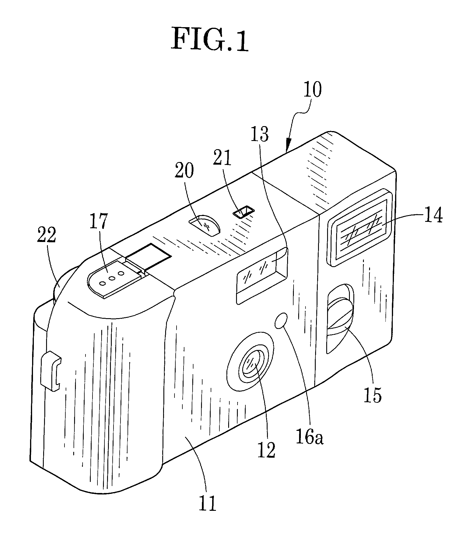
[0026] As shown in FIG. 1, a film unit is comprised of a housing 10 and a wrapping label 11 rolled around the housing 10. A taking lens 12, a viewfinder 13, a flash projector 14, a flash changeover plate 15 and a photometry window 16a are provided on front wall of the housing 10. A shutter button 17, a frame counter 20 and an indication light guide 21 are provided on a top wall of the housing 10, and a part of a winding dial 22 is exposed in a back wall of the housing 10.

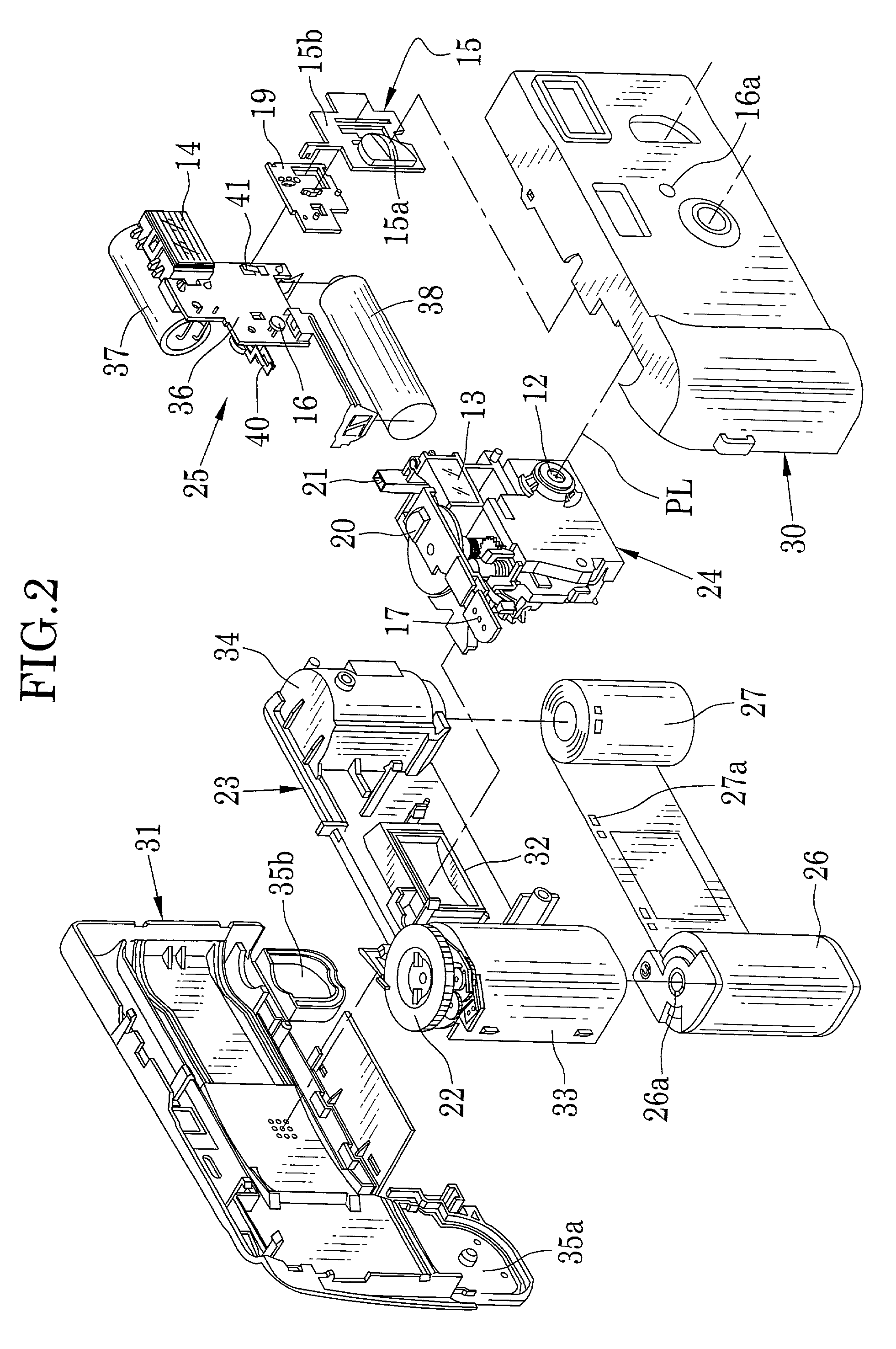
[0027] As shown in FIG. 2, a photo film cassette 26 and a photo film 27 are previously loaded inside the housing 10. The housing 10 includes a basic portion 23, an exposure unit 24, a flash device 25, a front cover 30 and a rear cover 31. The exposure unit 24 and the flash device 25 are removably attached to the front side of the basic portion 23.

[0028] The basic portion 23 is comprised of an exposure opening 32 for determining the frame region of the photo film 27, a cassette chamber 33 for containing the photo fil...


PUM


Abstract

A photo diode and a resistor are connected to each other in series. A gate of a FET is connected to the connection of the photo diode and the resistor. When a photometry switch is turned on, the photo diode generates a photo current according to a subject brightness. A potential difference is generated between the both terminal of the resistor. When the subject brightness is less than a threshold level, the FET is not turned on because of low potential difference of the resistor. When a subject brightness is equal to or more than the threshold level, the FET is turned on because of high potential difference of the resistor. A first transistor turned to be in a state opposite to the FET and a second transistor turned on and off according the state of the first transistor are provided. When the FET is turned off, the second transistor is turned on, and a solenoid is powered. The solenoid moves a stop plate out of an optical axis such that an exposure is taken through a large stop opening. When the FET is turned on, the second transistor is turned off, so the solenoid is not driven. Since the stop plate is set on the optical axis, an exposure is taken through a stop-down opening.

Description

[0001] 1. Field of the Invention[0002] The present invention relates to an automatic exposure control device of a camera, more particularly, the present invention relates to an automatic exposure control device for changing over a size of a stop opening according to subject brightness.[0003] 2. Background Arts[0004] Lens-fitted photo film units having pre-loaded photo films are widely sold as one kind of simple cameras. In the lens-fitted photo film unit (hereinafter referred to as film unit), it is unnecessary to load and take out the photo film, so the film unit makes it possible to photograph by simple operation. Moreover, a fixed-focus lens and a shutter mechanism the shutter speed of which is fixed are used in the film unit in order to reduce the manufacturing cost.[0005] The exposure value is constant when the aperture size and the shutter speed are fixed. In severe photographing condition, there is a case in which an exposure amount is out of the latitude of the photo film, s...

Claims


Application Information

Patent Timeline
IPC IPC(8): G03B7/085G03B7/095
CPCG03B7/085G03B7/095
Inventor HATA, YUKITSUGU
Owner FUJIFILM CORP
Why Eureka
Try Eureka