Method for brazing aluminum alloy-assembled articles within a short period of time and a filler alloy usable at low temperature

a technology of aluminum alloy and assembly, which is applied in the direction of manufacturing tools, sintering apparatus, other domestic objects, etc., can solve the problems of deteriorating the function of flux, affecting the usability of conventionally used filler alloys at high temperature, and affecting the performance of the core alloy, so as to achieve sufficient anti-corrosion properties, enhance anti-corrosion properties, and reduce the effect of deterioration

Inactive Publication Date: 2002-09-12
DENSO CORP +1
View PDF2 Cites 19 Cited by
  • Summary
  • Abstract
  • Description
  • Claims
  • Application Information

AI Technical Summary

Benefits of technology

[0011] (1) A method for brazing aluminum alloy-assembled articles within a short period of time, which comprises brazing aluminum alloy-assembled articles with a filler alloy having a liquidus temperature of 540.degree. C. or lower and a difference of temperature between the liquidus temperature and the solidus temperature being 100.degree. C. or lower, wherein the highest temperature reached in the assembled articles at the time of heating for brazing is set 40.degree. C. or more higher than the liquidus temperature but 585.degree. C. or lower,
[0012] (2) The method for brazing aluminum alloy-assembled articles within a short period of time according to the aforesaid item (1), wherein elevation of the temperature after exceeding the liquidus temperature is continued without keeping the article at a fixed temperature,

Problems solved by technology

(2) At the time of brazing, Mn deposition in the core alloy has been formed a solid solution again so that thermal conductivity of the core alloy is deteriorated to damage thermal characteristics of the heat exchanger.
In addition, Mg is diffused onto the surface of the brazing sheet to deteriorate the function of flux at the time of brazing.
Thus, the conventionally used filler alloy usable at high temperature involved various problems.
However, the filler alloy had a problem that it did not have a sufficient corrosion resistance.

Method used


Image

  • Method for brazing aluminum alloy-assembled articles within a short period of time and a filler alloy usable at low temperature
  • Method for brazing aluminum alloy-assembled articles within a short period of time and a filler alloy usable at low temperature
  • Method for brazing aluminum alloy-assembled articles within a short period of time and a filler alloy usable at low temperature

Examples


example 1

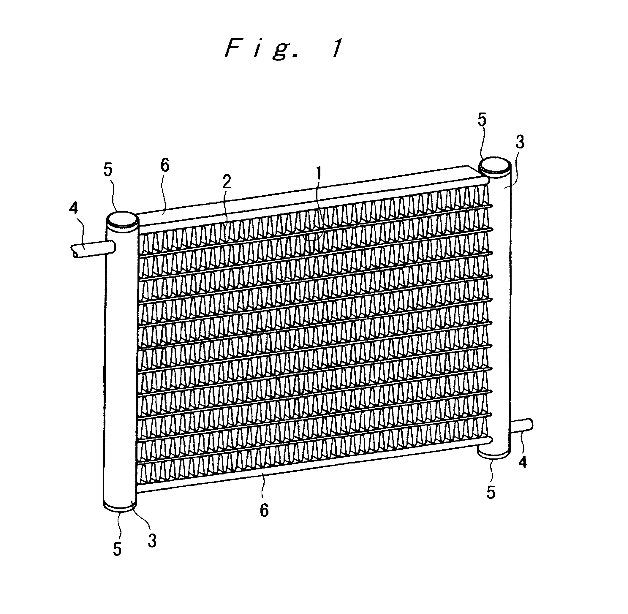
[0053] A core for heat-exchanger as shown in FIG. 1 was assembled and heated for brazing under the temperature conditions defined by the brazing method of the present invention.

[0054] A 1050 alloy plate having a thickness of 1.6 mm and a width of 16 mm was used as tube 1, a 3003 alloy plate to which 1% of Zn had been added having a plate thickness of 0.07 mm and a width of 16 mm was used as a fin 2, a 3003 alloy plate having a plate thickness of 1.2 mm was used as a header pipe 3, a 3003 alloy plate having a thickness of 1 mm was used as a pipe 4, a 3003 alloy plate having a thickness of 1 mm was used as an end cap 5, and a 3003 alloy plate having a thickness of 1.2 mm was used as a side plate 6. In the header pipe 3, holes were processed for thrusting the tube 1 or pipe 4 therein.

[0055] The tube 1 and the side plate 6 were previously precoated with powders of a filler alloy as shown in Table 1 (the powders having average particle size of 35 .mu.m prepared according to the atomizing...

example 2

[0062] As shown in FIG. 11, a brazing sheet 10 was prepared by rolling joint a sacrificial material (JIS 7072 Alloy of Al--Zn series) 8 in a thickness ratio of 10% onto one side of a core alloy (JIS 3003 Alloy of Al--Mn series) 7 and laminarly applying a filler alloy usable at low temperature, having a composition defined in the present invention, 9 powder (atomized powder of an average particle size of 35 .mu.m) incorporated with an organic binder onto the other side of the core material. A JIS 3003 Alloy plate 11 was brought into contact perpendicularly on the filler alloy usable at low temperature 9 layer of the brazing sheet 10, and the contact portion was coated with Cs flux. This structure was kept for 10 minutes in a furnace in nitrogen gas atmosphere kept at a temperature by 5.degree. C. higher than the liquidus temperature whereby the brazing sheet 10 and the JIS 3003 Alloy plate 11 were brazed.

example 3

[0066] A composite plate (0.25 mm in thickness) prepared by roll jointing a sacrificial material (JIS 7072 Alloy) on one side of a core alloy (JIS 3003 Alloy) at a thickness ratio of 10% was subjected to seam brazing while turning the core alloy front side to form a pipe material having a length of 150 mm. A filler alloy powder having a composition defined in the present invention was incorporated with an organic binder and applied on the surface of the pipe material and the pipe material formed a tube. As shown in FIG. 12, a plurality of the pipes are arranged in parallel and a corrugated fin (JIS 3003 Alloy+Zn of 1 wt %) of 70 .mu.m in thickness was placed between each tube 12, the whole structure was fixed with a jig and kept for 10 minutes in a furnace in nitrogen gas atmosphere at a temperature by 5.degree. C. higher than the liquidus temperature to braze the tube 12 and the fin 13.


PUM

PropertyMeasurementUnit
liquidus temperatureaaaaaaaaaa
solidus temperatureaaaaaaaaaa
liquidus temperatureaaaaaaaaaa

Abstract

A method for brazing aluminum alloy-assembled articles with a filler alloy having a liquidus temperature of 540.degree. C. or lower and a difference of temperature between the liquidus temperature and the solidus temperature being 100.degree. C. or lower, wherein the highest temperature reached in the assembled article at the time of heating for brazing being set 40.degree. C. or more higher than the liquidus temperature but 585.degree. C. or lower. An aluminum alloy-filler alloy usable at low temperature for brazing, which comprises Si in an amount of 4.0 wt % to 8.0 wt %, Zn in an amount of 7.0 wt % to 20.0 wt % and Cu in an amount of 10.0 wt % to 35.0 wt %, with the balance being made of aluminum.

Description

[0001] This is a continuation of PCT Application PCT / JP01 / 01909, filed Mar. 12, 2001. The prior PCT application was not published in English under PCT Article 21(2).FIELD[0002] This invention relates to a method for brazing an aluminum alloy-assembled article within a short period of time wherein a heating time for brazing is significantly shortened, and to filler alloy usable at low temperature and excellent in corrosion resistance.BACKGROUND[0003] From the past, a brazing method for aluminum alloy-assembled articles has adopted a process wherein an assembled article is formed with a brazing sheet composed of a core alloy (an alloy of Al--Mn series) both surfaces of which has been clad with a filler alloy of Al--Si series or one of the surfaces of which has been clad with a sacrificial material (an alloy of Al--Zn series) and the other surface of which has been clad with a filler alloy (an alloy of Al--Si series), and integrated in a furnace by heating the article at a temperature ...

Claims


Application Information

Patent Timeline
Patent Type & Authority Applications(United States)
IPC IPC(8): B23K1/00B23K1/19B23K35/28
CPCB23K1/0012B23K1/19B23K2103/10B23K2101/14B23K35/288
Inventor OHARA, NOBUAKIDOKO, TAKEYOSHISHIMIZU, MASAKINOHIRA, SATOSHINISHIKAWA, HIROSHIOGAWA, HIROSHI
Owner DENSO CORP
Why Eureka
Try Eureka