Optical disk device

a technology of optical disk and optical disk, which is applied in the direction of instruments, disposition/mounting of heads, recording signal processing, etc., can solve the problems of inability to determine, and inability to detect the absolute position

Inactive Publication Date: 2003-04-10
TEAC CORP
View PDF3 Cites 22 Cited by
  • Summary
  • Abstract
  • Description
  • Claims
  • Application Information

AI Technical Summary

Problems solved by technology

However, when seeking of the optical pickup is effected through DC motor control, for example, it is not possible to detect where the optical pickup is, that is, it is not possible to detect the absolute position of the optical pickup unless the address can be reproduced.
In a mechanism in which seeking is effected through DC motor control, when a track deviation occurs due to disturb...

Method used


Image

  • Optical disk device
  • Optical disk device
  • Optical disk device

Examples


Embodiment Construction

[0030] Preferred embodiments of the present invention will now be described with reference to the drawings with a DVD-RAM drive as an example.

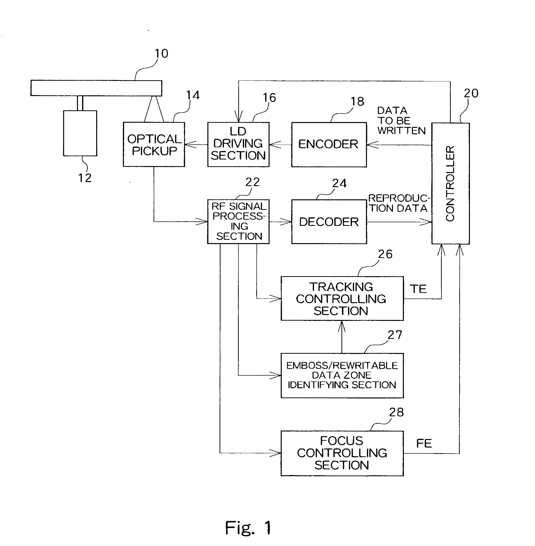
[0031] FIG. 1 is a block diagram showing a structure of an optical disk device according to the present embodiment.

[0032] An optical disk 10 is rotationally driven by a spindle motor 12 through a CAV (or CLV) method.

[0033] An optical pickup 14 is placed to oppose the optical disk 10, and irradiates laser light of a writing power onto the optical disk 10 to write data and laser light of a reproducing power onto the optical disk 10 to reproduce written data. During the writing process, data to be written which is supplied from the controller 20 is modulated by an encoder 18 and is converted into a driving signal by an LD driving section 16. A laser diode (LD) of the optical pickup 14 is driven by the driving signal. During the reproducing process, a four-segment photodetectors within the optical pickup 14 converts the amount of return light into...


PUM


Abstract

An optical disk device in which data is written to or reproduced from an optical disk having an area which contains a header section and another area which does not contain a header section. When a track deviation of an optical pickup occurs, it is detected whether or not a signal representing the header section is contained in the return light signal from the optical disk. When a signal representing the header section is contained in the return light signal, it is determined that the optical pickup is located in an area which contains a header section and tracking is controlled through a push-pull method etc. On the other hand, when a signal representing the header section is not contained in the return light signal from the optical pickup, it is determined that the optical pickup is located in an area which does not contain a header section and tracking is controlled through differential phase detection etc.

Description

[0001] 1. Field of the Invention[0002] The present invention relates to an optical disk device, and in particular, to a recovery process from a track deviation.[0003] 2. Description of the Related Art[0004] In an optical disk, tracking is controlled so that data can be written or reproduced while laser light is irradiated on an approximate center area of an information recording track. More specifically, an amount of return laser light from an optical disk is detected, a variation in the amount of return light corresponding to the displacement from the approximate center of the track is detected as a tracking error signal, and an optical pickup is driven along the radial direction of the optical disk by a servo system based on the tracking error signal. Various methods are known for controlling the tracking including a three-spot method, push-pull method, difference push-pull method, and DPD (Differential Phase Detection).[0005] On the other hand, in a DVD-RAM, as shown in FIG. 8A, ...

Claims


Application Information

Patent Timeline
IPC IPC(8): G11B7/005G11B7/085G11B7/09
CPCG11B7/0906G11B7/0901
Inventor MIKAMI, TORU
Owner TEAC CORP
Why Eureka
Try Eureka