Heat storage tank in cooling water circuit

a technology of cooling water circuit and heat storage tank, which is applied in the direction of machines/engines, heating types, lighting and heating apparatus, etc., can solve the problems of deterioration of the sealing performance of the heat storage tank and the readily deteriorated rubble material

Inactive Publication Date: 2004-09-30
DENSO CORP
View PDF9 Cites 5 Cited by
  • Summary
  • Abstract
  • Description
  • Claims
  • Application Information

AI Technical Summary

Problems solved by technology

However, in this case, the O-ring is exposed to both outside air and the high-temperature cooling water due to a vibration of a vehicle and a water pressure in the cooling water circuit.
I...

Method used


Image

  • Heat storage tank in cooling water circuit
  • Heat storage tank in cooling water circuit
  • Heat storage tank in cooling water circuit

Examples


Embodiment Construction

[0019] A preferred embodiment of the present invention will be described hereinafter with reference to the accompanying drawings.

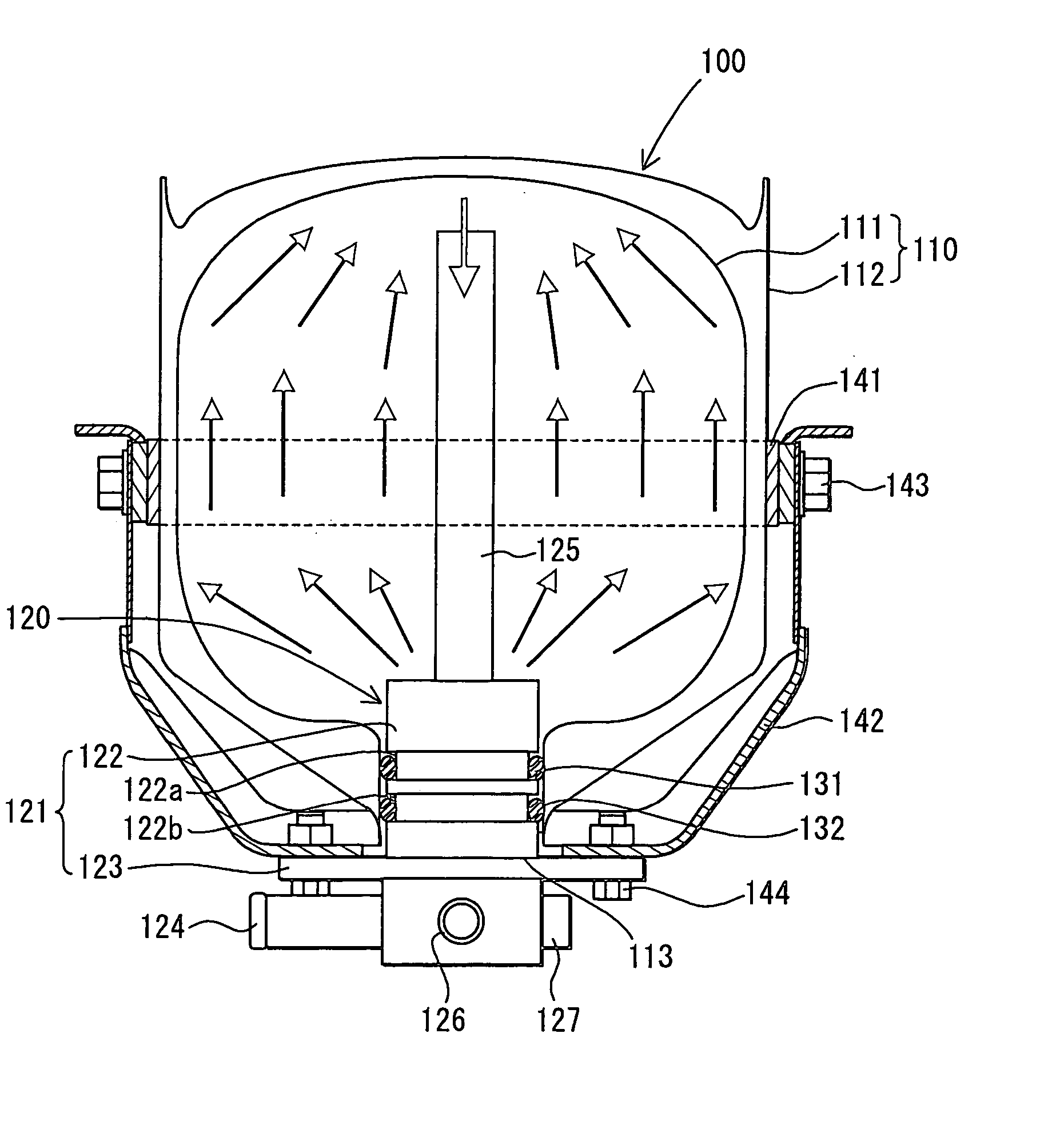
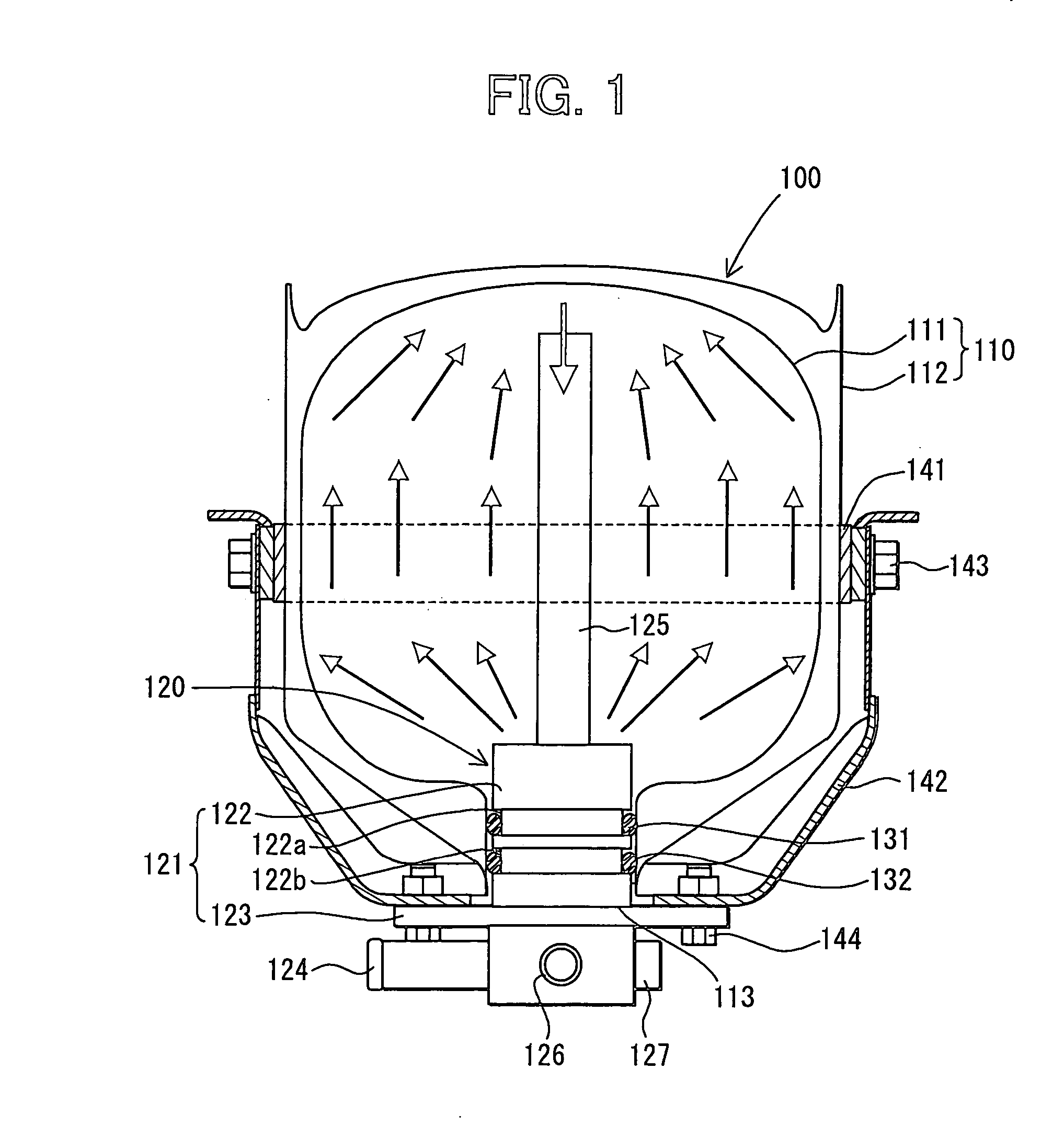
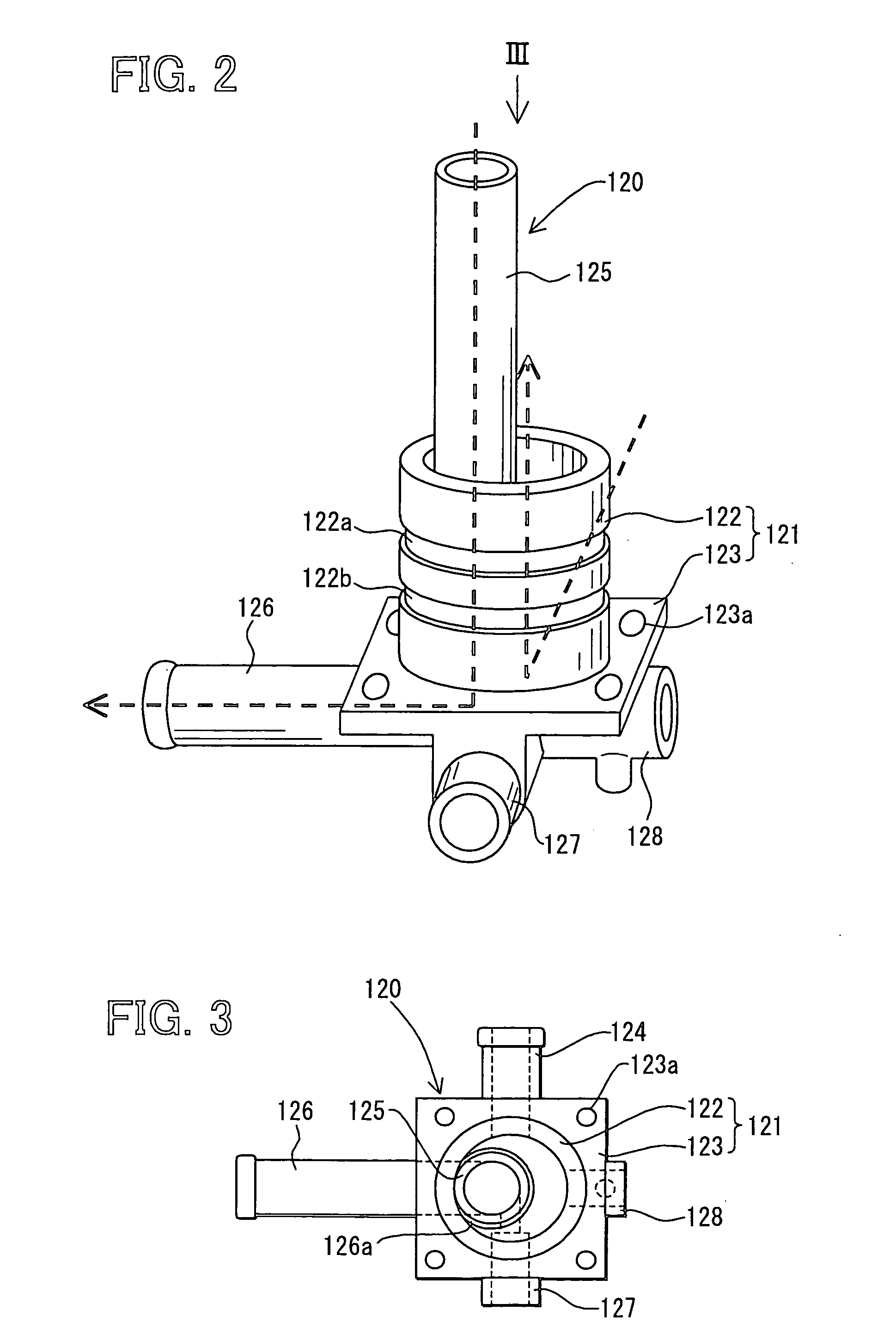
[0020] In this embodiment, a heat storage tank 100 according to the present invention is typically used for a cooling water (coolant) circuit of a water-cooled engine (liquid-cooled engine). As shown in FIG. 1, the heat storage tank 100 includes a tank body 110, and a cooling-water passage portion 120. The tank body 110 stores cooling water therein while performing a thermal insulation. The tank body 110 includes an inner tank portion 111 made of stainless steel having a high corrosion resistance, and an outer tank portion 112 provided to cover the inner tank portion 111. The inner and outer tank portions 111, 112 are connected together by welding or brazing while an approximate vacuum state is provided between the inner and outer tank portions 111, 112 so that a heat insulation layer is provided between the inner and outer tank portions 111, 112.

[0021] Th...


PUM


Abstract

A heat storage tank includes a tank body having a cylindrical opening portion at one end side, and a coolant passage portion for defining therein flow passages communicating with the tank body. The tank body stores a coolant of a liquid-cooled engine therein while being thermal insulated, and the coolant flows into and flows out of the tank body through the flow passages. The coolant passage portion includes an insertion portion that is inserted into the opening portion in its axial direction. At least two O-rings are provided between the opening portion of the tank body and the insertion portion to seal a clearance therebetween, and are lined in the axial direction to be separated from each other in the axial direction by a predetermined distance. Accordingly, the heat storage tank can improve sealing performance of the coolant.

Description

[0001] This application is related to Japanese Patent Application No. 2003-93915 filed on Mar. 31, 2003, the content of which is hereby incorporated by reference.[0002] 1. Field of the Invention[0003] The present invention relates to a heat storage tank which stores a coolant of a liquid-cooled engine such as a water-cooled engine while being thermal-insulated.[0004] 2. Description of Related Art[0005] For example, as disclosed in JP-A-2002-188442 (corresponding to U.S. Pat. No. 6,477,990), a heat storage tank is disposed in a cooling water circuit of a water-cooled engine, and stores high-temperature cooling water (coolant) therein in an engine operation. Then, the heat storage tank discharges the stored high-temperature cooling water to the engine at the next engine starting, thereby improving warming-up performance of the engine. Alternatively, heating performance of a heating unit can be improved using the cooling water (hot water) from the heat storage tank as a heat source.[00...

Claims


Application Information

Patent Timeline
IPC IPC(8): F01P3/20B60H1/00F01P11/02F01P11/20F28D20/00
CPCB60H1/00492F01P2070/00F01P2011/205F01P11/20
Inventor ITO, SHIGEOTOYOSHIMA, TAKASHIYOSHIKAWA, SHIGETAKA
Owner DENSO CORP
Why Eureka
Try Eureka