Prismatic battery

Inactive Publication Date: 2004-09-30
SANYO ELECTRIC CO LTD
View PDF2 Cites 130 Cited by
  • Summary
  • Abstract
  • Description
  • Claims
  • Application Information

AI Technical Summary

Benefits of technology

0009] An object of the present invention is to provide a prismatic battery which is easy to assembl

Problems solved by technology

Therefore, it is not possible to avoid misalignment between the terminals (91), (92) and t

Method used


Image

  • Prismatic battery
  • Prismatic battery
  • Prismatic battery

Examples


Embodiment Construction

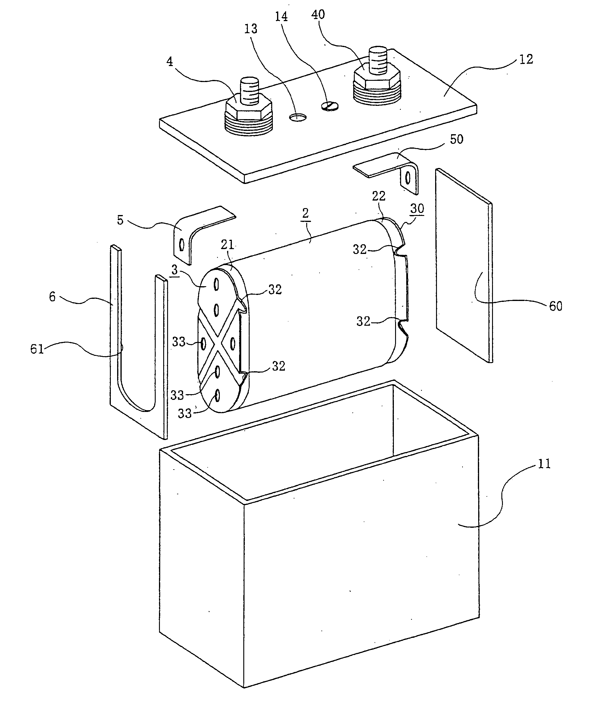
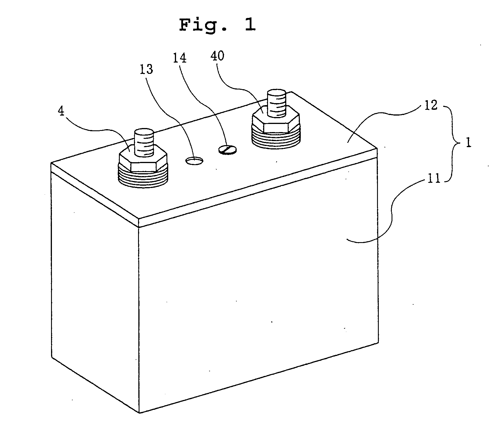
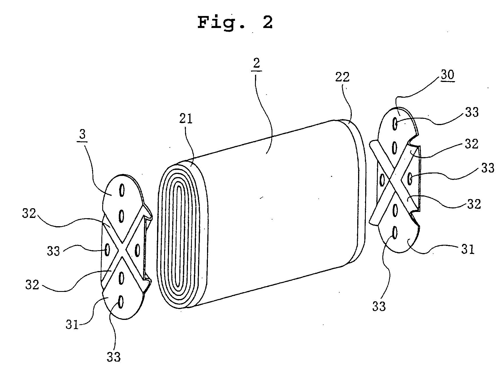
[0039] In the prismatic battery of the present invention, one end of each of the lead members (5), (50) is welded to the current collector plates (3), (30) and another end of each of the lead members (5), (50) is welded to the electrode terminals (4), (40) or is held by the electrode terminals (4), (40).

[0040] Even if there happens to be a variations in the positions of the current collector plates (3), (30) on the electrode (2), the variations can be overcome by bending or deformation of the lead members (5), (50) at a step of assembling the battery because the current collector plates (3), (30) and the electrode terminals (4), (40) are connected by the flexible lead members (5), (50).

[0041] Therefore, a process to connect the current collector plates (3), (30) and the electrode terminals (4), (40) with the lead members (5), (50) is easy. Furthermore, connected areas of the current collector plates (3), (30) and the lead members (5), (50) and the electrode terminals (4), (40) and t...


PUM

PropertyMeasurementUnit
Elasticityaaaaaaaaaa

Abstract

A prismatic battery wherein a wound electrode (2) is housed in a battery can (1) including a sealing plate (12) fixed onto an opening of a prismatic case (11) with the outer surface of the electrode (2) aligned with the bottom of the prismatic case (11). Current collector plates (3), (30) are placed at both ends of the wound electrode (2) where edges (21), (22) of a pair of positive and negative electrodes project. The current collector plates (3), (30) are connected to a pair of positive and negative electrode terminals (4), (40). The current collector plates (3), (30) and the electrode terminals (4), (40) are connected by flexible flexible lead members (5), (50).

Description

[0001] The present invention relates to a prismatic battery comprising a wound electrode housed in a prismatic battery can.[0002] A lithium secondary battery having a high energy density (Wh / Kg) has recently been developed as a power source for portable electronic equipment, electric vehicles, and the like. A prismatic battery has especially become attractive because of a high volume energy density (Wh / P).[0003] A prismatic battery as shown in FIG. 6 houses a wound electrode (8), which is a power generation element, sideways in a rectangular parallelepiped case (80) (See Japanese Patent Laid-open Publication No. 2002-93402). L-shaped current collector members (9), (90) are connected to opposite ends of the electrode (8). A pair of positive and negative terminals (91), (92) are formed on respective current collector members (9), (90) to take out generated power.[0004] A sealing plate (not shown in FIG. 6) is fixed on an opening of the case (80). The terminals (91), (92) pass through ...

Claims


Application Information

Patent Timeline
IPC IPC(8): H01M6/10H01M10/04H01M10/05H01M10/0587H01M50/534H01M50/536H01M50/538H01M50/55H01M50/553H01M50/566H01M50/627
CPCH01M2/0217H01M2/0426H01M2/263H01M2/30Y10T29/49114H01M10/0431H01M10/052Y02T10/7011H01M2/36Y02E60/10H01M50/103H01M50/169H01M50/538Y02P70/50H01M50/55H01M50/627H01M50/553H01M50/534H01M50/536H01M50/566A61F13/505B32B7/08B32B5/26B32B27/12B32B5/08B32B27/40B32B2262/0276B32B2262/0261B32B2255/02B32B2255/26B32B2375/00B32B2555/00
Inventor AKITA, HIROYUKIKITAO, HIDEKISATOH, KOUICHIFUNAHASHI, ATSUHIRONOHMA, TOSHIYUKI
Owner SANYO ELECTRIC CO LTD
Why Eureka
Try Eureka