Nasal interface and system including ventilation insert

a ventilation insert and nasal interface technology, applied in the field of nasal interfaces, can solve the problems of obstructive sleep apnea syndrome generally experiencing fragmented sleep, inadequate amount of oxygen flowing into the lungs, and preventing leakage, so as to achieve the effect of preventing leakag

Active Publication Date: 2005-03-10
SALTER LABS LLC
View PDF7 Cites 88 Cited by
  • Summary
  • Abstract
  • Description
  • Claims
  • Application Information

AI Technical Summary

Benefits of technology

[0019] Yet further exemplary embodiments of the present invention provide a ventilation interface system including a cannula adapted to be connected to a source of ventilation gas via a feed tube and a y-connector, the cannula forming a first portion of an input gas flow passage to supply the ventilation gas to the user. A nasal insert adapted to be inserted the nares of the user, the nasal insert forming a second portion of the input gas flow passage from the cannula to a distal end of the

Problems solved by technology

However, in those individuals having a relatively smaller sized throat passage, the narrowed throat passage prohibits the adequate amount of oxygen from flowing into the lungs.
Additionally, one or more of a nasal obstruction, a relatively large tongue, and/or certain shapes of the palate and/or the jaw of the individual further prohibit the adequate amount of oxygen from flowing into the lungs.
As a result, the individual suffering from obstructive sleep apnea syndrome generally experiences fragmented sleep that is not restful.
The fragmented sleep results in one or more of excessive and/or inappropriate daytime drowsiness, headache, weight gain or loss, limited attention span, memory loss, poor judgment, personality changes, lethargy, inability to maintain concentration, and/or depression.
Further, prior to, during, and/or subsequent to certain medical procedures and/or medical treatments, an individual can be unable to receive the adequate amount of oxygen.
Additionally, the conventional tubing will collapse if it is bent around the ears with the flat side against the side of the users head.
Thus, the use of such a conventional harness and tubing results in a number of disadvantages.
For example, because pressure must be applied between the required harness and the head of the individual to maint

Method used


Image

  • Nasal interface and system including ventilation insert
  • Nasal interface and system including ventilation insert
  • Nasal interface and system including ventilation insert

Examples


Embodiment Construction

[0033] Examples of one or more exemplary embodiments of the present invention will now be described with reference to the drawings, wherein like reference numbers throughout the several views identify like and / or similar elements.

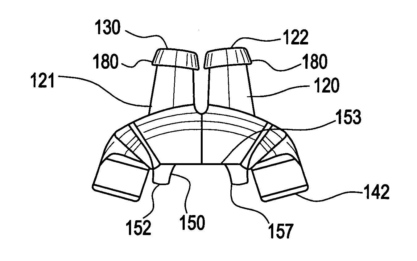
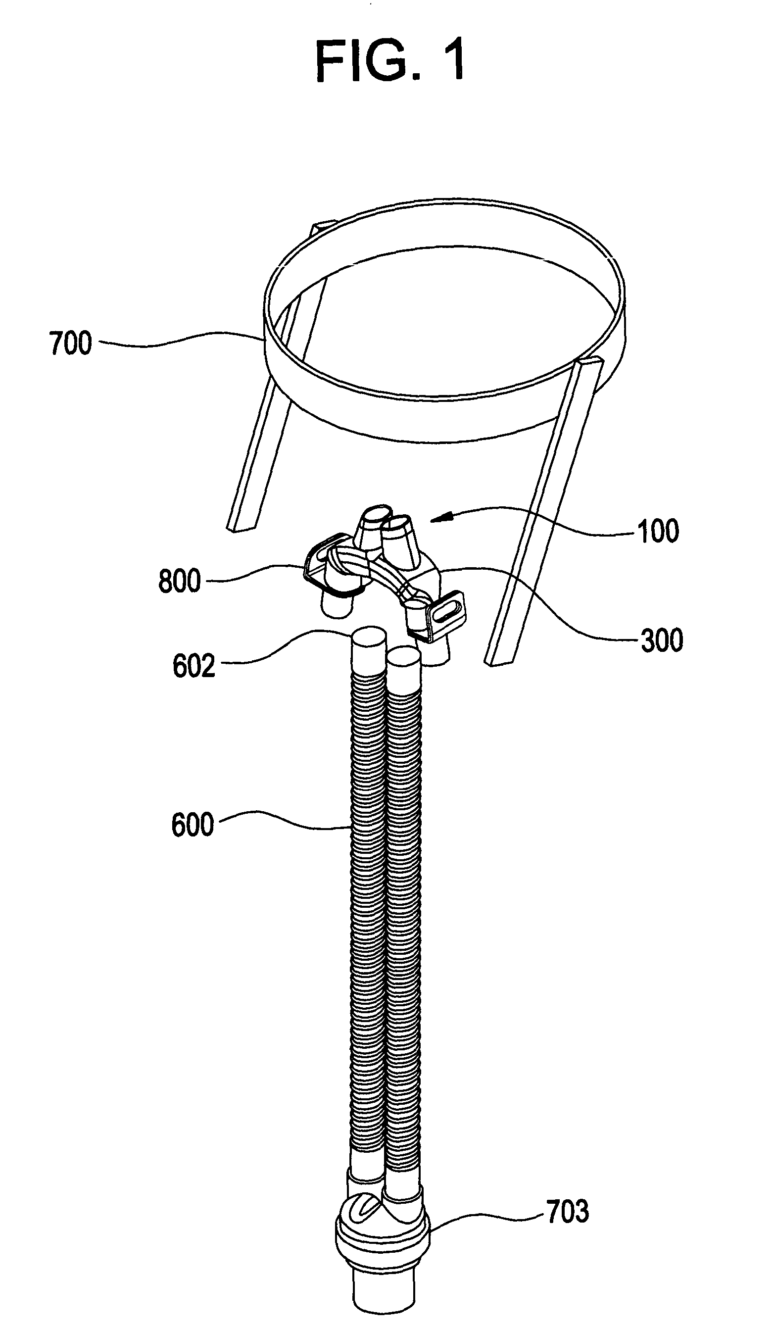
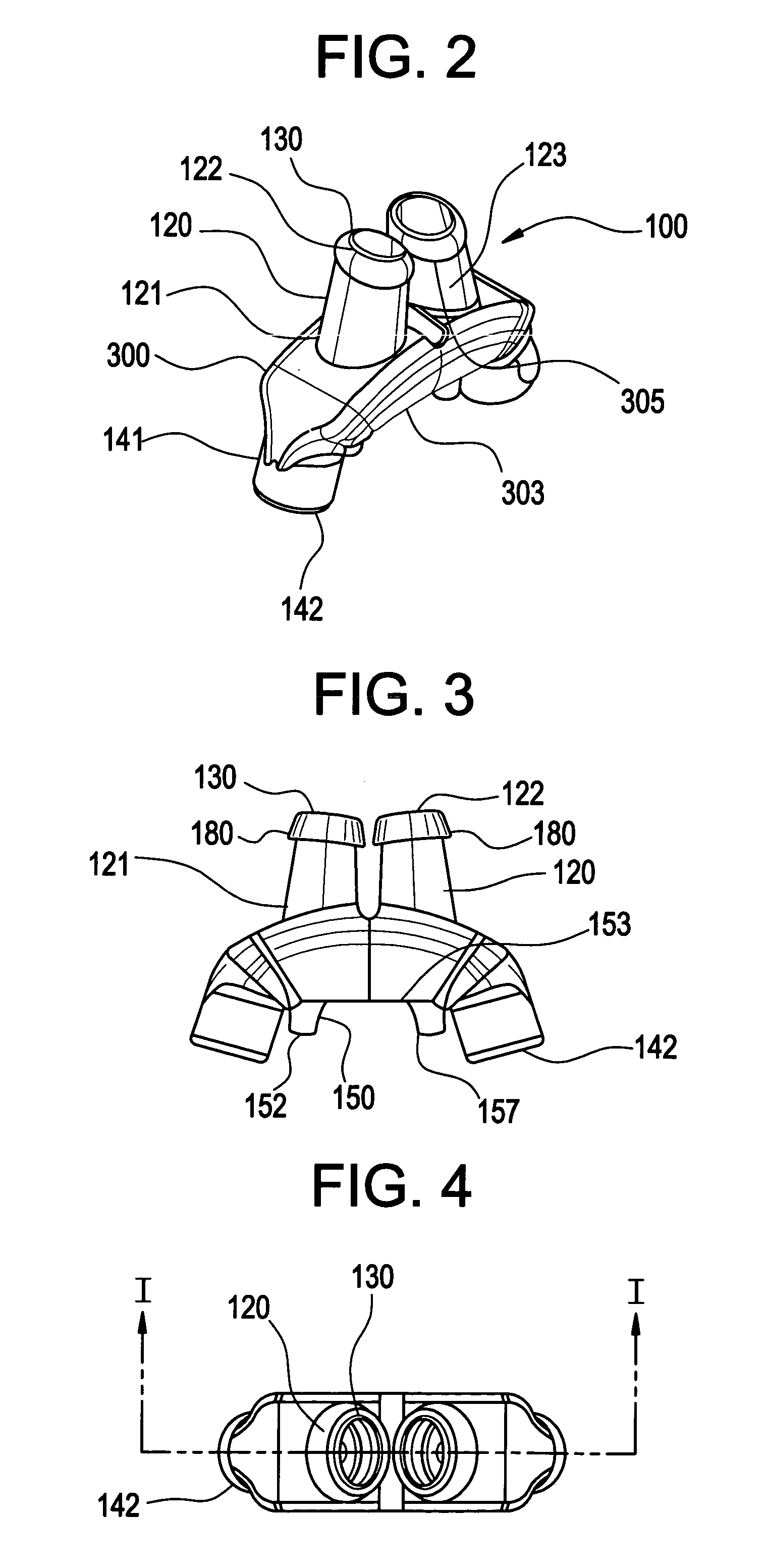
[0034] Generally referring to FIGS. 1-6, in an exemplary embodiment, the present invention can provide a ventilation interface system adapted to be inserted into a nares of a user to secure the interface. A cannula 300 adaptable to be connected to a source of ventilation gas (not shown) forms a first portion 141 of an input gas flow passage to supply the ventilation gas to the user. Nasal inserts 120 are adapted to be inserted into the nares of the user forms a second portion 123 of the input gas flow passage from the cannula to a distal end of the nasal insert 130. A seal portion 122 optionally adapted to engage a portion of the nares of the user is positioned at the distal end 130 of the nasal insert. The first 141 and second portions 123 of the input ga...


PUM


Abstract

A ventilation or CPAP interface system adapted to be inserted into a nares of a user to secure the interface. A cannula adapted to be connected to a source of ventilation gas forms a first portion of an input gas flow passage to supply the ventilation gas to the user. A nasal insert adapted to be inserted the nares of the user forms a second portion of the input gas flow passage from the cannula to a distal end of the nasal insert. A seal portion adapted to engage a portion of the first naris is provided adjacent the distal end of the nasal insert. Ventilation interface system may optionally include feed tubes, y-connector, tube holder, and headgear.

Description

CROSS-REFERENCE TO RELATED APPLICATIONS [0001] This application is related in subject matter to U.S. Pat. No. 6,478,026, PCT Patent Application Number PCT / US03 / 24590, filed Aug. 6, 2003, U.S. patent application Ser. Nos. 10 / 610,594 filed Jul. 2, 2003, 10 / 044,925 filed Jan. 15, 2002, 10 / 096,795 filed Mar. 14, 2002, and 10 / 392,959 filed Mar. 21, 2003, all to Thomas J. Wood, the disclosures of which are incorporated by reference herein in their entirety.BACKGROUND OF THE INVENTION [0002] 1. Field of the Invention [0003] Exemplary embodiments of the invention are directed to a ventilation interface, and more particularly to a ventilation interface including a cannula forming a first portion of an input gas flow passage and a nasal insert forming a second portion of the input gas flow passage, the first and second portions of the input gas flow passage disposed at an obtuse angle to one another. [0004] 2. Discussion of Related Art [0005] Obstructive sleep apnea syndrome (commonly referre...

Claims


Application Information

Patent Timeline
IPC IPC(8): A42BA61M15/00A61M15/08A61M16/00A61M16/06A62B7/00A62B17/00A62B18/02A62B18/08
CPCA61M16/0683A61M16/0666A61M16/0833
Inventor WOOD, THOMAS J.HERNANADEZ, SHARASHER, BRUCE M.
Owner SALTER LABS LLC
Why Eureka
Try Eureka