Flat panel display

a technology of flat panel display and display screen, which is applied in the direction of machine supports, electric apparatus casings/cabinets/drawers, instruments, etc., can solve the problems of laborious user tasks and inconvenient user points of view, and achieve the effect of more convenien

Inactive Publication Date: 2005-03-10
WATONGA TECH
View PDF5 Cites 38 Cited by
  • Summary
  • Abstract
  • Description
  • Claims
  • Application Information

AI Technical Summary

Benefits of technology

[0008] It is therefore an object of the invention to provide a flat panel display to let the user move the display module upwards, downwards, forwards, and backwards relative to the base. The invention allows the user to pull closer or push further the display module to adjust the viewing distance. The invention also allows the user to move the display module upwards and downwards to suitable height and angle for the user's sight. Compared with flat panel display in the art, the invention offers more convenience.

Problems solved by technology

However, when the user wants to adjust the viewing distance by pushing further or pulling closer the display module, the user needs to move the entire flat panel display; it is a laborious task for the user.
The user needs to adjust the viewing height and viewing angle in order to see the display from the flat panel display 20; it is very inconvenient from the user's point of view.

Method used


Image

  • Flat panel display
  • Flat panel display
  • Flat panel display

Examples


embodiment 1

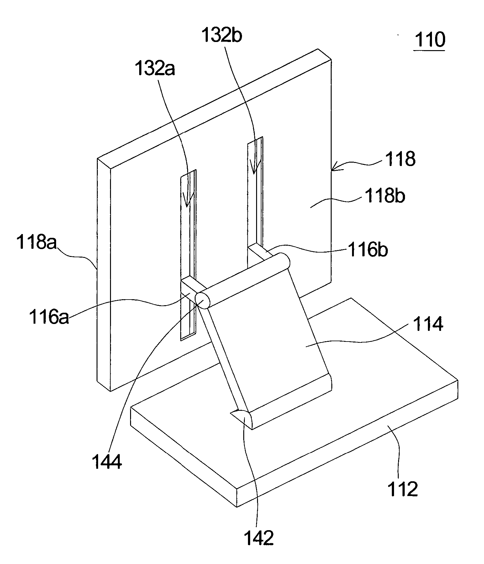
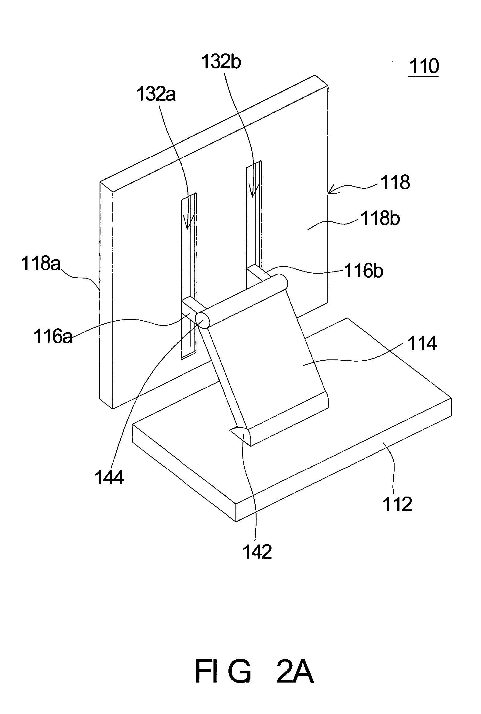
[0025] Referring to FIG. 2A and FIG. 2B, the 3-D diagram and the lateral view of the first embodiment according to the invention are respectively shown. In FIG. 2A and FIG. 2B, the flat panel display 110 includes at least a base 112, a supporting arm 114, a display module 118, and two slide-brackets 116a and 116b. The display module 118 has a front 118a and a back 118b. In this embodiment, there are two slide-brackets 116a and 116b, but the numbers of slide-brackets are not limited to this embodiment as shown in FIG. 2A; it could be one or more than one, depending on different requirements. A display panel 120 could be installed on the front 118a of the display module 118 as shown in FIG. 2B, and it is used to display information. The supporting arm 114 has a first end and a second end. The first end of the supporting arm 114 is hinged to the base 112 in a way that the supporting arm 114 can rotate relative to the base 112, along the direction pointed out by the arrow 150 of FIG. 2B...

embodiment 2

[0035] Referring to FIG. 7, a lateral view of the flat panel display according to a second embodiment of the invention is shown. In FIG. 7, the flat panel display has a base 812, a supporting arm 814, at least a slide-bracket 816, a load board 855 and a display module 818. The display module 818 has a front 818a and a back 818b. A display panel 820 is installed on the front 818a of the display module 818. The supporting arm 814 has a first end and a second end. The first end of the supporting arm 814 is connected to the base 812 by a hinge 842 so that the supporting arm 814 can rotate relative to the base 812, along the direction pointed out by the arrow 850 of FIG. 7.

[0036] The slide-bracket 816 has a first end and a second end. The first end of the slide-bracket 816 hinges to the second end of the supporting arm 814 by a second hinge 844 so that the slide-bracket 816 can rotate relative to the supporting arm 814, along the direction pointed out by the arrow 860 of FIG. 7. The loa...


PUM


Abstract

A flat panel display includes a base, a supporting arm, a slide-bracket and a display module. The supporting arm has a first end and a second end. The first end of the supporting arm is hinged to the base so that the supporting arm can rotate relative to the base. The slide-bracket has a first end and a second end. The first end of the slide-bracket is hinged to the second end of the supporting arm so that the slide-bracket can rotate relative to the supporting arm. The display module is connected to the second end of the slide-bracket. Therefore, the display module can move relative to the base along with the movement of the supporting arm, and the display module can slide relative to the slide-bracket.

Description

[0001] This application claims the benefit of Taiwan application Serial No. 92121728, filed Aug. 7, 2003, the subject matter of which is incorporated herein by reference. BACKGROUND OF THE INVENTION [0002] 1. Field of the Invention [0003] The invention relates in general to a flat panel display, and more particularly to a flat panel display with a display module that can move upwards, downwards, forwards, and backwards relative to the base. [0004] 2. Description of the Related Art [0005] Nowadays, desktop computers have become indispensable necessities for people in their day-to-day life. Generally speaking, a desktop computer includes at least a computer case with the components inside, and a computer screen that can be either a cathode ray tube (CRT) screen or a flat panel display. Because flat panel displays have the advantages of less weight, smaller size, no radiation, and smooth display over the CRT screens, they are popular computer screens. [0006] Referring to FIG. 1A and FI...

Claims


Application Information

Patent Timeline
Patent Type & Authority Applications(United States)
IPC IPC(8): F16M11/10F16M11/24
CPCF16M11/046F16M11/10F16M11/2021Y10S248/92F16M2200/047Y10S248/919F16M11/24
Inventor CHU, YAO-WEN
Owner WATONGA TECH
Why Eureka
Try Eureka