Electrical Candle with Micro-Control Means

a microcontroller and electric candle technology, applied in the direction of lighting support devices, coupling device connections, and devices with built-in power, etc., can solve the problems of fire accidents, carbon dioxide produced and polluted air, and it's not convenient to find socket sets

Inactive Publication Date: 2008-07-03
TSAI SAM
View PDF10 Cites 42 Cited by
  • Summary
  • Abstract
  • Description
  • Claims
  • Application Information

AI Technical Summary

Benefits of technology

[0008]Besides, the main body further comprises a containing space, which at least one power supply element could be put in, to couple with the circuit module. The power supply element could be a battery. In addition, the main body also comprises a cover plate, coupled with the containing space to prevent the power supply element from dropping out of the containing space.

Problems solved by technology

A conventional candle usually emits light by burning its wick, and may cause some deficiencies, for examples after burning the wick, consequently carbon dioxide produced and the air polluted.
Besides, sometimes a fire accident occurred when the conventional candle is not set up well.
It's not convenient to find a socket set, although the electrical candle could help to decrease the possibility of accidents occurred.
Although the above-mentioned electrical candles may improve some shortcomings of conventional candles, they are still inconvenient.

Method used


Image

  • Electrical Candle with Micro-Control Means
  • Electrical Candle with Micro-Control Means
  • Electrical Candle with Micro-Control Means

Examples


Embodiment Construction

[0016]The foregoing and other objects, features and advantages of the present invention will be more readily understood upon consideration of the following preferred embodiment's description of the invention, taken in conjunction with the following drawing.

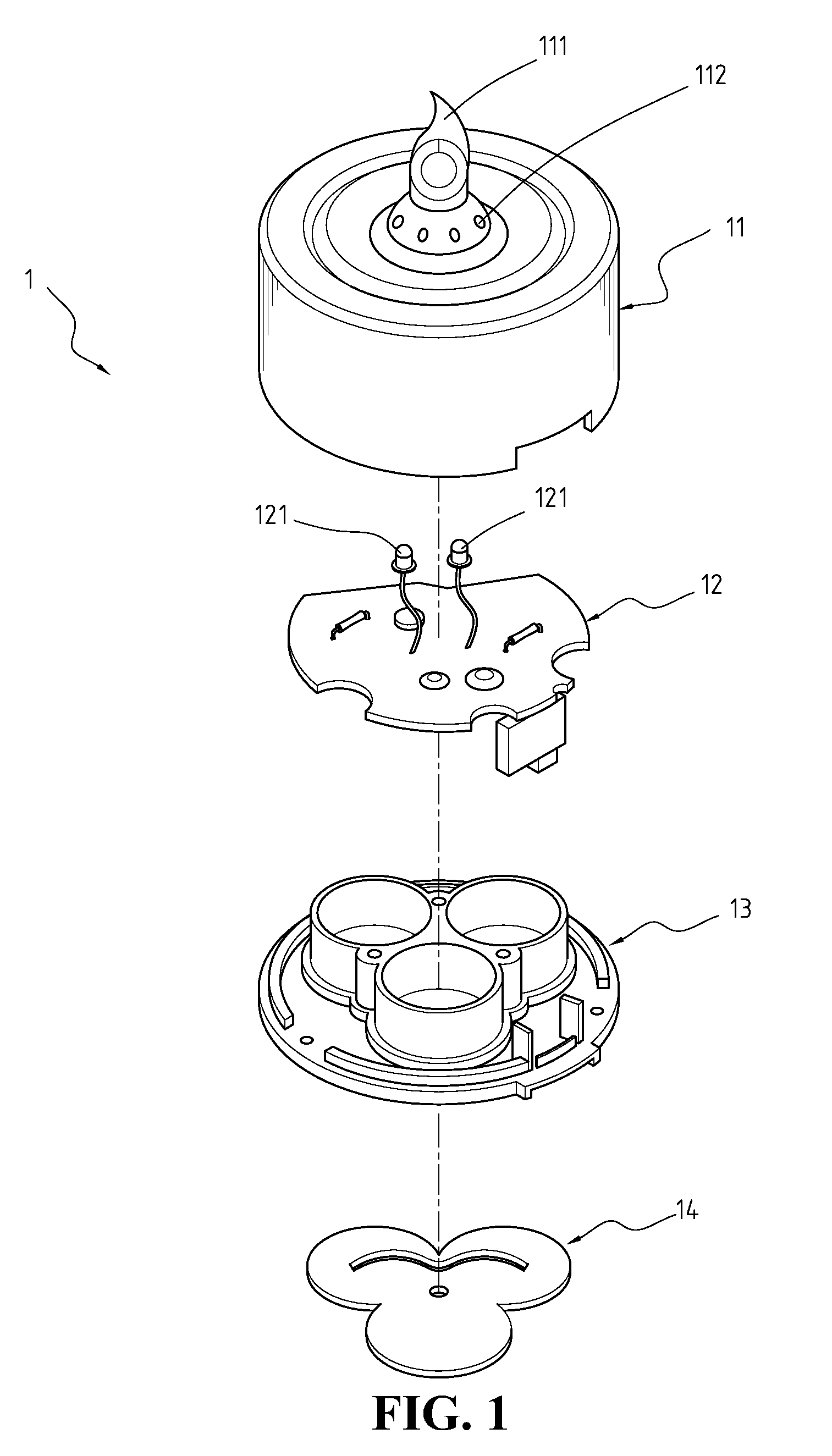
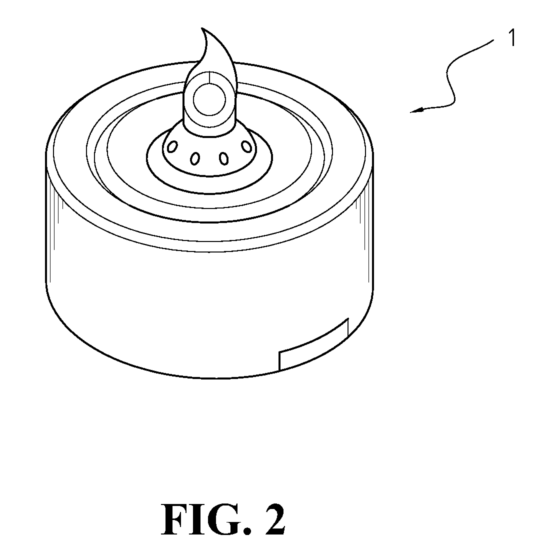
[0017]The present invention is to provide an improved electrical candle with micro-control means, wherein the electrical candle comprises a main body 1 and a base body 2. With reference to FIG. 1-2, illustrating the main body 1 includes a shell 11 and a circuit module 12, and the shell 11 including a flame-shaped cover member 111 and a plurality of holes 112. The plurality of holes 112 is set around the flame-shaped cover member 111, and the flame-shaped cover member 111 is made by transparent or translucent materials. The circuit module 12, inside the shell 11, including an illuminant 121 and a micro switch (unshown). The illuminant 121, comprising at least one light-emitting diode, is enclosed in the flame-shaped cover member 11...


PUM


Abstract

The electrical candle with micro-control means comprising a main body and a base body. The main body includes a shell and a circuit module, and the shell including a flame-shaped cover member and a plurality of holes. The circuit module, inside the shell, includes an illuminant and a micro switch. The base body includes a hollow to contain the main body. The characteristic is that the electrical candle turned on and off by an external force which actuates the micro switch to control power supply. The external force could be airflow-control, voice-control and vibrating so that it is easy for users to utilize the electrical candle. Therefore, the present invention provides a new and improved electrical candle for people to use with more convenience.

Description

FIELD OF THE INVENTION[0001]The present invention relates to an illumination device, and more particularly, to an electrical candle with micro-control means.BACKGROUND OF THE INVENTION[0002]A conventional candle usually emits light by burning its wick, and may cause some deficiencies, for examples after burning the wick, consequently carbon dioxide produced and the air polluted. Besides, sometimes a fire accident occurred when the conventional candle is not set up well.[0003]U.S. Pat. No. 5,601,360 published on Feb. 11, 1997, titled “Plug-in Electrical Candle for a Window Sill” disclosed an electrical candle is in combination with a low-voltage bulb at the top and a pair of prongs at the bottom, and the prongs are engaged to the contacts of the low-voltage socket installed in a window sill. It's not convenient to find a socket set, although the electrical candle could help to decrease the possibility of accidents occurred.[0004]People's Republic of China Patent Publication No. CN266...

Claims


Application Information

Patent Timeline
Patent Type & Authority Applications(United States)
IPC IPC(8): F21S4/00H01R33/02H01R33/46
CPCF21S6/001F21S9/02F21Y2101/02F21V23/0442F21W2121/00F21V15/01F21Y2115/10
Inventor TSAI, SAM
Owner TSAI SAM
Why Eureka
Try Eureka