Image temporal change detection and display method and apparatus

a detection method and image technology, applied in the field of image systems, can solve problems such as insufficient robustness of approaches, image contrast poor, and inability to incorporate confidence levels

Active Publication Date: 2005-05-26
GE MEDICAL SYST GLOBAL TECH CO LLC
View PDF10 Cites 100 Cited by
  • Summary
  • Abstract
  • Description
  • Claims
  • Application Information

AI Technical Summary

Benefits of technology

[0008] The present invention provides a novel technique for analysis of images created at different points in time designed to respond to such needs. The technique may be used for images from any suitable modality or imaging system, including complex imaging systems used in medical part and parcel inspection, but also conventional photographic systems. The present technique provides for accessing image data representative of a subject created at different points in time, the points in time being separated by any useful span, from fractions of a second to months or even years. The technique also greatly facilitates the workflow and efficiency in carrying out the process of comparison and analysis. In particular, CAD techniques may be applied both for the original screening of image data for analysis, as well as to launch such screening where appropriate.

Problems solved by technology

However, simple subtraction results in images of poor contrast.
Moreover, such approaches are not sufficiently robust when two initial images are acquired using different techniques or modalities.
Moreover, such approaches do not incorporate an indication of a confidence level in the magnitude of the dissimilarity measurement.
Any errors in registration of the two images may result in significantly large values in the dissimilarity image due to the presumption that much more significant changes have occurred in the images or between the images due to the misalignment.
Such artifacts and the lack of standard anatomical features renders radiographic interpretation of temporal subtracted images challenging for a radiologist or other user, especially when given the unfamiliarity of such users with the appearance of such images.
The images can, of course, be superimposed or otherwise associated with the original images, although developments in the field have not risen to a level as yet to satisfactory in this regard.

Method used


Image

  • Image temporal change detection and display method and apparatus
  • Image temporal change detection and display method and apparatus
  • Image temporal change detection and display method and apparatus

Examples


Embodiment Construction

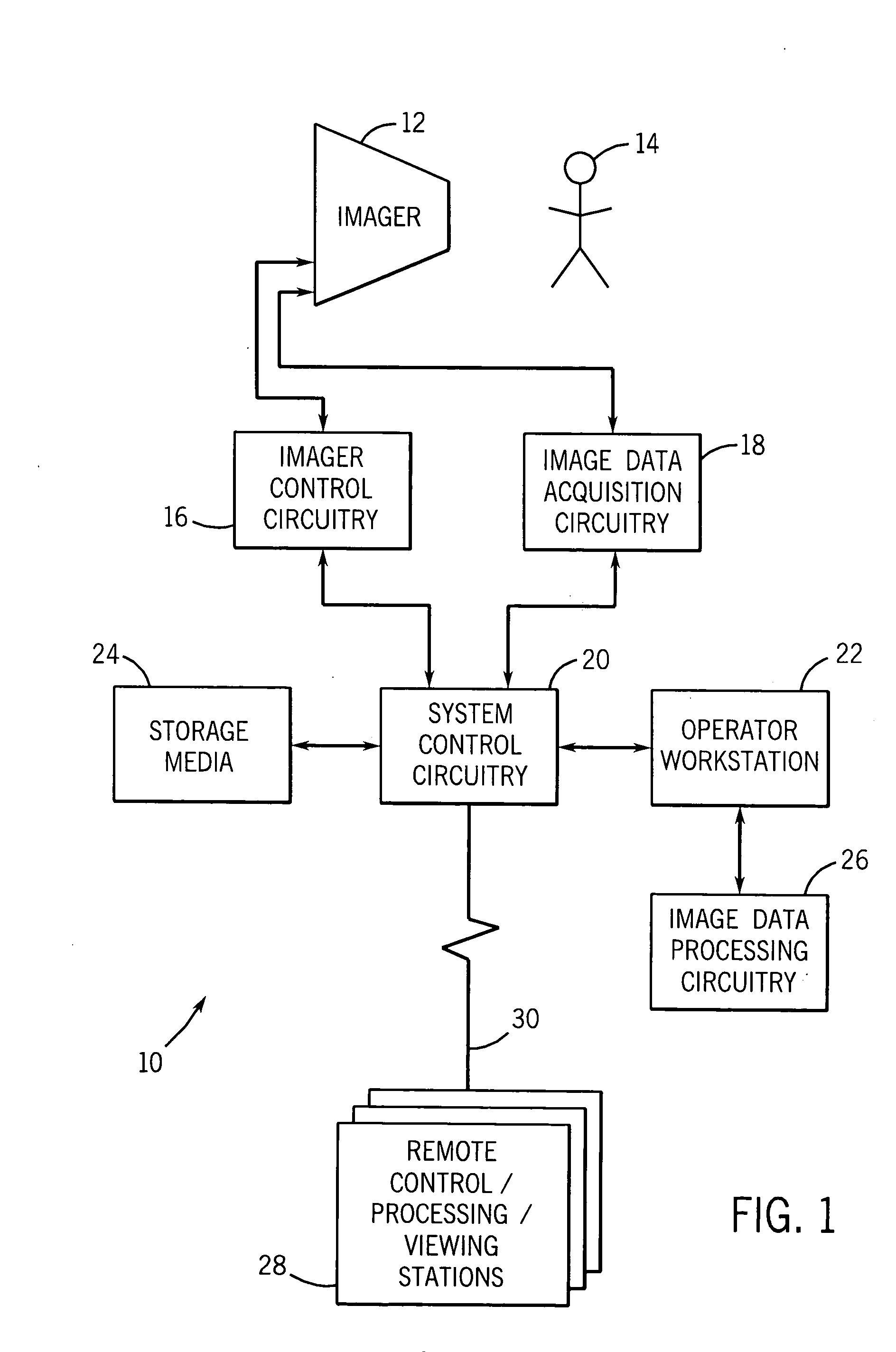
[0018] Turning now to the drawings and referring first to FIG. 1, an imaging system 10 is illustrated generally as including an imager 12 for creating image data of a subject 14. Although a human figure is generally shown as the subject 14, it should be borne in mind that any appropriate subject could be imaged. In the present context, for example, the subject may be human or animal, animate or in-animate, such as manufactured parts, naturally occurring subjects and so forth. Indeed, the imaging system 10 may be any suitable type of system that produces digitized image data based upon some imaging physics. In the medical imaging context, as elsewhere, such imaging systems may include MRI systems, PET systems, CT system, tomosythesis systems, X-ray systems, ultrasound systems, among many other imaging modalities. The systems may also include conventional photographic imaging systems, that produce digitized image data based upon received radiation of any suitable bandwidth or frequenc...


PUM


Abstract

A technique is provided for analysis of image datasets acquired at different points in time. Computer aided algorithms are implemented for identification and classification of features of interest, and for comparison of such features which have evolved over time as represented by the image data. The algorithms may be specifically adapted to analyze temporal change images. Such algorithms may also be used to efficiently launch temporal change analysis only when particular features of interest are possibly present in the image data.

Description

BACKGROUND OF THE INVENTION [0001] The present invention relates generally to a field of imaging systems. In particular, the invention relates to a technique for analyzing image data to recognize features of interest and comparing resulting analyses with similar analyses performed on image data collected at different points in time in computationally and workflow-efficient manners. [0002] Many applications exist for digital imagery. Such applications range from medical diagnostic imaging to part detection and analysis, parcel screening, and so forth. Similarly, many different types of imaging systems are currently available, some of which span certain of these applications. Imaging systems range from traditional photographic systems to much more complex magnetic resonance imagine (MRI) system, computed tomography (CT) systems, positron emission tomography (PET) systems, ultrasound systems, X-ray systems, and so forth. In each of these systems, some type of image data acquisition cir...

Claims


Application Information

Patent Timeline
Patent Type & Authority Applications(United States)
IPC IPC(8): A61B5/00A61B5/055A61B6/00A61B6/03A61B8/13G06T1/00G06T11/00
CPCA61B5/055A61B5/7264A61B6/00A61B8/13G06T7/0012A61B6/548G06T11/005G06T2207/10072G06T2207/30004G06T2211/412G06T7/2033G06T7/0016G06T7/246
Inventor SABOL, JOHN M.FUNG, MAGGIE MEI-KEIBATTLE, VIANNEY PIERREAVINASH, GOPAL B.
Owner GE MEDICAL SYST GLOBAL TECH CO LLC
Why Eureka
Try Eureka