One-way rotational transfer mechanism, and a lens barrel incorporating the same

a technology of rotational transfer mechanism and lens barrel, which is applied in the direction of camera focusing arrangement, gearing, printers, etc., can solve the problems of difficult to increase the number of rollers serving as torque transfer members, complicated structure, and uneven transfer of driving force of af motor to the distance adjustment ring, etc., to achieve greater torque, simple structure, and transfer a torque

Inactive Publication Date: 2005-06-02
RICOH IMAGING COMPANY
View PDF4 Cites 25 Cited by
  • Summary
  • Abstract
  • Description
  • Claims
  • Application Information

AI Technical Summary

Benefits of technology

[0011] The present invention provides a one-way rotational transfer mechanism which is simple in structure, capable of transferring a torque from the rotary input shaft to the rotary output shaft smoothly and reliably, capable of transferring a greater torque from the rotary input shaft to the rotary output shaft, and capable of making the rotary output shaft rotate smoothly upon a torque being applied thereto after the rotary output shaft is rotated upon application of a torque to the rotary output shaft.
[0012] The present invention further provides a lens barrel in which a movable lens group is moved selectively by a driving force of a motor or a torque of a hand-operated ring, wherein the driving force of the motor is securely transferred to the movable lens group to move the movable lens group when the motor is driven to rotate, and further wherein the movable lens group can be moved smoothly by a driving force of the hand-operated ring after the movable lens group is moved by a driving force of the motor.
[0034] It is desirable for the associating device to prevent the friction-decreasing relative movement between the clutch member and the rotary output shaft when the relative rotational torque, upon the rotary input shaft being rotated, is smaller than or equal to the predetermined torque. When the relative rotational torque becomes larger than the predetermined torque, the associating device temporarily allows the friction-decreasing relative movement between the clutch member and the rotary output shaft, and subsequently allows the clutch member to return to an initial position thereof by the biasing force of the second biasing device to hold the clutch member at the initial position thereof.
[0046] The lens barrel can include a distance adjustment ring which moves the movable lens group along the optical axis by one of a torque of the hand-operated ring and a torque of the rotary output shaft; and a second one-way rotational transfer mechanism which transfers the torque of the hand-operated ring to the distance adjustment ring, and prevents the torque of the distance adjustment ring from being transferred to the hand-operated ring, the second one-way rotational transfer mechanism being positioned between the distance adjustment ring and the hand-operated ring.

Problems solved by technology

However, in the lens barrel disclosed in Japanese laid-open patent publication H8-177878, a driving force of the AF motor is not smoothly transferred to the distance adjustment ring when the AF motor is driven because of heavy backlash which occurs upon rotation of the rotary input shaft (upon startup of the motor).
In the one-way rotational transfer mechanism disclosed in the aforementioned Japanese patent publication H11-202181, the structure thereof is complicated.
Moreover, it is difficult to increase the number of rollers serving as torque transfer members due to the complicated structure of the one-way rotational transfer mechanism, and accordingly, the torque which is transferred from the rotary input shaft to the hollow-cylindrical rotary output shaft when the rotary input shaft is driven to rotate cannot be increased very much.
Furthermore, in the lens barrel disclosed aforementioned Japanese laid-open patent publication H08-177878, there is a possibility of the one-way rotational transfer mechanism becoming incapable of securely transferring torque from the AF motor to the distance adjustment ring to thereby make it impossible to perform an autofocusing operation when the AF motor is driven.

Method used


Image

  • One-way rotational transfer mechanism, and a lens barrel incorporating the same
  • One-way rotational transfer mechanism, and a lens barrel incorporating the same
  • One-way rotational transfer mechanism, and a lens barrel incorporating the same

Examples


Embodiment Construction

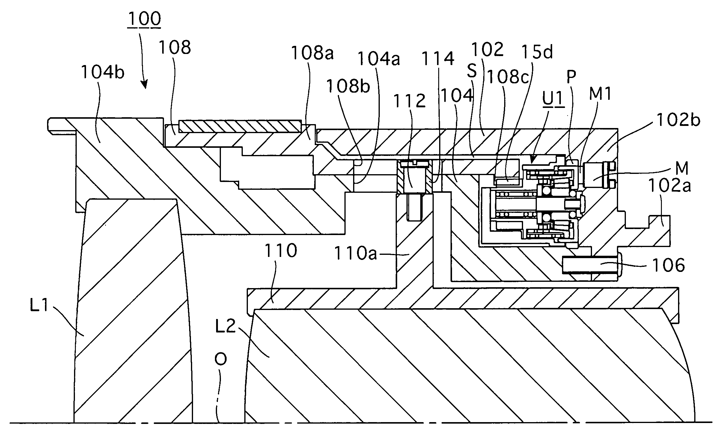
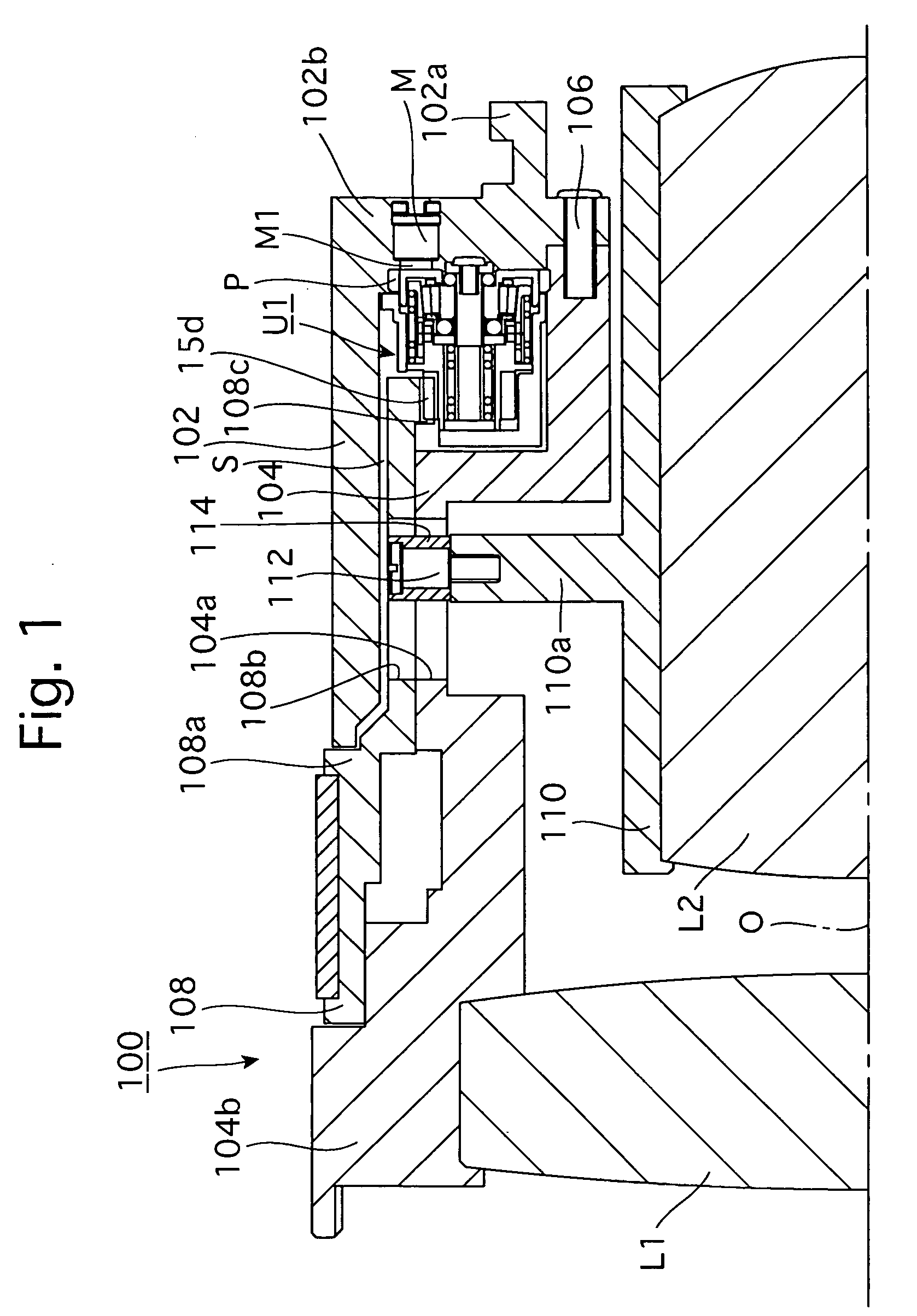
[0076]FIGS. 1 through 7 show a first embodiment of a lens barrel which is can be switched between an autofocus (AF) mode and a manual focus (MF) mode for an autofocus camera.

[0077] Firstly, the overall structure of this embodiment of the lens barrel 100 will be discussed hereinafter.

[0078] In the following descriptions, the front and rear of the lens barrel 100 correspond to the left and right sides of the lens barrel 100 as viewed in FIG. 1, respectively. The lens barrel 100 is provided with a first stationary ring 102 having a mount portion (bayonet mount portion) 102a at a rear end of the first stationary ring 102. The mount portion 102a is mounted to a body mount provided on a camera body (not shown) via a bayonet engagement when the lens barrel 100 is attached to the camera body. The lens barrel 100 is provided inside the first stationary ring 102 with a second stationary ring 104, the rear end of which is fixed to the rear end of the first stationary ring 102 by set screws 1...


PUM


Abstract

A one-way rotational transfer mechanism includes a rotary input shaft, a rotary output shaft, a clutch member, a differential rotating member, a circumferentially-uneven-width-space forming portion formed on the rotary input shaft, a torque transfer member, and an associating device. The torque transfer member wedges between the circumferentially-uneven-width-space forming portion and the clutch member while making the torque transfer member contact the clutch so that the rotary input shaft and the clutch member become integral upon rotation of the rotary input shaft. The associating device causes the clutch member to transfer torque thereof to the rotary output shaft, and the clutch member to release engagement of the rotary input shaft with the clutch member when the rotary output shaft is rotated so that a relative rotational torque greater than a predetermined torque determined by a shape of the associating device.

Description

BACKGROUND OF THE INVENTION [0001] 1. Field of the Invention [0002] The present invention relates to a one-way rotational transfer mechanism having a rotary input shaft and a rotary output shaft which are concentrically arranged, wherein rotation of the rotary input shaft is transferred to the rotary output shaft when the rotary input shaft is rotated, but rotation of the rotary output shaft is not transferred to the rotary input shaft when the rotary output shaft is rotated. The present invention further relates to a lens barrel which incorporates such an one-way rotational transfer. [0003] 2. Description of the Related Art [0004] Among conventional one-way rotational transfer mechanisms having a rotary input shaft and a hollow-cylindrical rotary output shaft positioned radially outside the rotary input shaft, wherein the rotary input shaft is driven by motor to transfer rotation of the rotary input shaft to the hollow-cylindrical rotary output shaft, a one-way rotational transfer ...

Claims


Application Information

Patent Timeline
Patent Type & Authority Applications(United States)
IPC IPC(8): F16D41/10F16D43/02F16H33/00F16H35/00F16H37/00G02B7/08
CPCF16D41/105Y10T74/19G02B7/08F16D43/02
Inventor HAMASAKI, TAKUJIIIKAWA, MAKOTO
Owner RICOH IMAGING COMPANY
Why Eureka
Try Eureka