Mount apparatus for image displaying device

a technology of mounting apparatus and image displaying device, which is applied in the field of mounting apparatus for image displaying device, can solve the problems that mount apparatus cannot freely control the image displaying device in the desired direction of a viewer, and mount apparatus cannot perform such an operation

Inactive Publication Date: 2005-06-16
LG ELECTRONICS INC
View PDF1 Cites 65 Cited by
  • Summary
  • Abstract
  • Description
  • Claims
  • Application Information

AI Technical Summary

Benefits of technology

[0016] An object of the present invention is to provide a mount apparatus for an image displaying device in which the image displaying device can be mounted at a fixed surface and can be freely controlled in direction.

Problems solved by technology

However, the mount apparatus cannot freely control the image displaying device in a viewer's desired direction since it just merely fixes the image displaying device to the wall surface.
For example, when it is intended to control the image displaying device in all directions in the state where the image displaying device is fixed to the wall surface, the mount apparatus cannot perform such an operation.

Method used


Image

  • Mount apparatus for image displaying device
  • Mount apparatus for image displaying device
  • Mount apparatus for image displaying device

Examples


Embodiment Construction

[0033] Reference will now be made in detail to the preferred embodiments of the present invention, examples of which are illustrated in the accompanying drawings. Wherever possible, the same reference numbers will be used throughout the drawings to refer to the same or like parts.

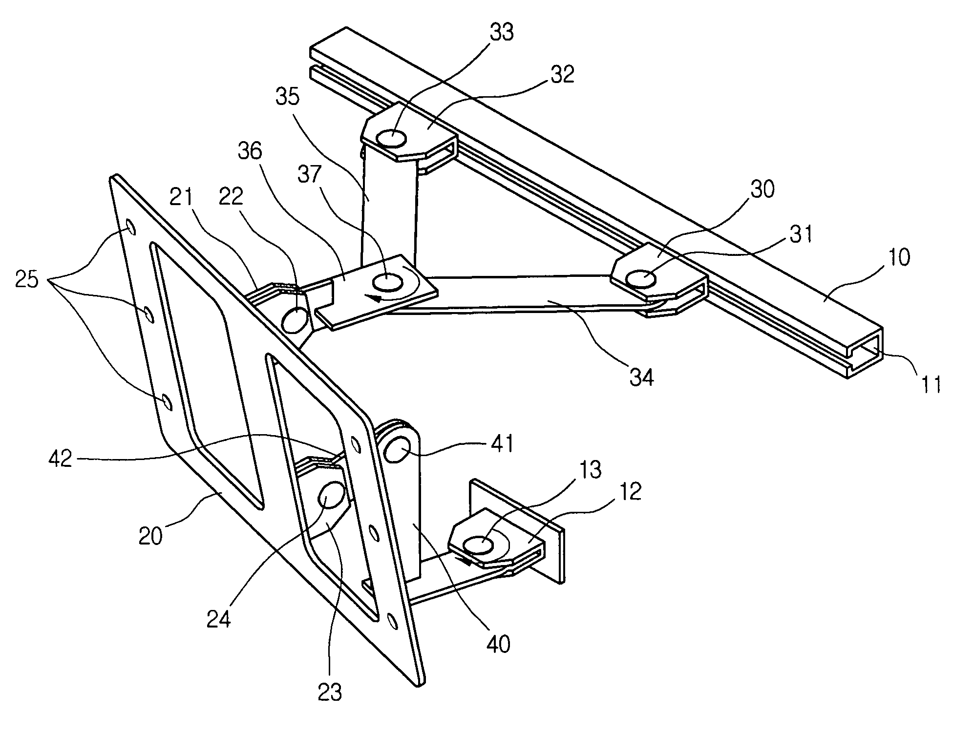
[0034]FIG. 4 is a perspective view illustrating a mount apparatus for an image displaying device according to the present invention.

[0035] The mount apparatus includes a set engaging unit engaged to a rear surface of the image displaying device; and a fixing unit engaged and fixed to a fixed surface such as a wall surface; and a connecting unit for connecting the set engaging unit with the fixing unit and vertically and horizontally controlling the image displaying device engaged to the set engaging unit.

[0036] First, as shown in FIG. 6, the set engaging unit includes a set engaging member 20; a first connecting unit 21 provided at a rear upper portion of the set engaging member 20; and a second connecti...


PUM


Abstract

A mount apparatus for an image displaying device is provided. The apparatus includes: a set engaging unit engaged to a rear surface of the image displaying device; a fixing unit fixed to a fixed surface; an upper connecting unit engaged with an upper portion of the set engaging unit to vertically rotate with respect to the upper portion of the set engaging unit, and slidably engaged to the fixing unit, thereby vertically rotating with respect to the upper portion of the set engaging unit depending on an up and down control of the image displaying device while varying an interval between the upper portion of the set engaging unit and the fixing unit; and a lower connecting unit for connecting a lower portion of the set engaging unit with the fixing unit and engaged with the lower portion of the set engaging unit to vertically rotate with respect to the lower portion of the set engaging unit.

Description

BACKGROUND OF THE INVENTION [0001] 1. Field of the Invention [0002] The present invention relates to a mount apparatus for an image displaying device, and more particularly, to a mount apparatus for an image displaying device in which a flat-type image displaying device can be mounted at a fixed surface such as a wall and can be easily controlled in angle. [0003] 2. Description of the Related Art [0004] Recently, a demand for a large-sized image displaying device such as a plasma display panel TV or a liquid crystal display TV is being rapidly increased. [0005] Such an image displaying device has an advantage of a small thickness, a lightweight and a large-sized screen in comparison to a cathode ray tube displaying device according to the related art. [0006] Specifically, a flat-type image displaying device has an advantage in that it can be mounted at a fixed surface such as a wall surface to maximize a utilization of space. Accordingly, a variety of mount apparatuses for mounting ...

Claims


Application Information

Patent Timeline
Patent Type & Authority Applications(United States)
IPC IPC(8): G06F1/16B60R11/00B60R11/02F16M11/12F16M13/02H04N5/64
CPCB60R11/0235B60R2011/0066B60R2011/0082B60R2011/0084B60R2011/0087Y10S248/922F16M11/12F16M11/2014F16M13/02H04N5/64F16M11/10G06F1/16
Inventor KIM, TAE HYUNG
Owner LG ELECTRONICS INC
Why Eureka
Try Eureka