Implant delivery assembly with expandable coupling/decoupling mechanism

a technology of coupling/decoupling mechanism and implant, which is applied in the field of surgical instruments, can solve the problems of difficult repositioning or retrieval of the coil, inaccurate placement of the coil, and electrolytic release of the coil

Pending Publication Date: 2005-07-14
STRYKER EURO OPERATIONS HLDG LLC +1
View PDF70 Cites 36 Cited by
  • Summary
  • Abstract
  • Description
  • Claims
  • Application Information

AI Technical Summary

Benefits of technology

[0013] The present invention provides a mechanical occlusive implant delivery assembly having a rapid response decoupling or detachment mechanism that does not effect significant migration of the implant during release. The assembly includes an occlusive implant device, such as an embolic coil, a pusher or device to carry the implant to the selected location, and an expandable mechanism that is expanded or contracted to release the implant at the selected site. The invention advantageously incorporates a release mechanism that simply involves unloading a locking force, which is preferably uniformly applied, thereby avoiding the transmission of any significant force to the implant during release. In addition, the locking members preferably have generally, smooth, rounded configurations so that they do not catch and dislodge previously positioned coils upon retraction.
[0017] an inflatable member having a first portion coupled to the distal section of the pusher and a second portion disposed in the tubular portion of the implant such that upon inflation of the inflatable member the implant and member tend to separate. More specifically, the coil slides off of the inflatable member. In addition to causing minimal post delivery migration of the implant, this construction provides an advantageously simple one-piece decoupling mechanism, which can be readily manufactured.
[0022] These configurations advantageously eliminate the need for auxiliary hydraulics.

Problems solved by technology

However, there are concerns when discharging the coil from the distal end of the catheter.
Inaccurate placement of the coil can be problematic because once the coil has left the catheter, it is difficult to reposition or retrieve the coil.
The only perceived disadvantage of this method is that the electrolytic release of the coil may require a period of time that may inhibit rapid detachment of the coil from the pusher.
Among the drawbacks of this system is that it involves generally complicated laser optic componentry.

Method used


Image

  • Implant delivery assembly with expandable coupling/decoupling mechanism
  • Implant delivery assembly with expandable coupling/decoupling mechanism
  • Implant delivery assembly with expandable coupling/decoupling mechanism

Examples


Embodiment Construction

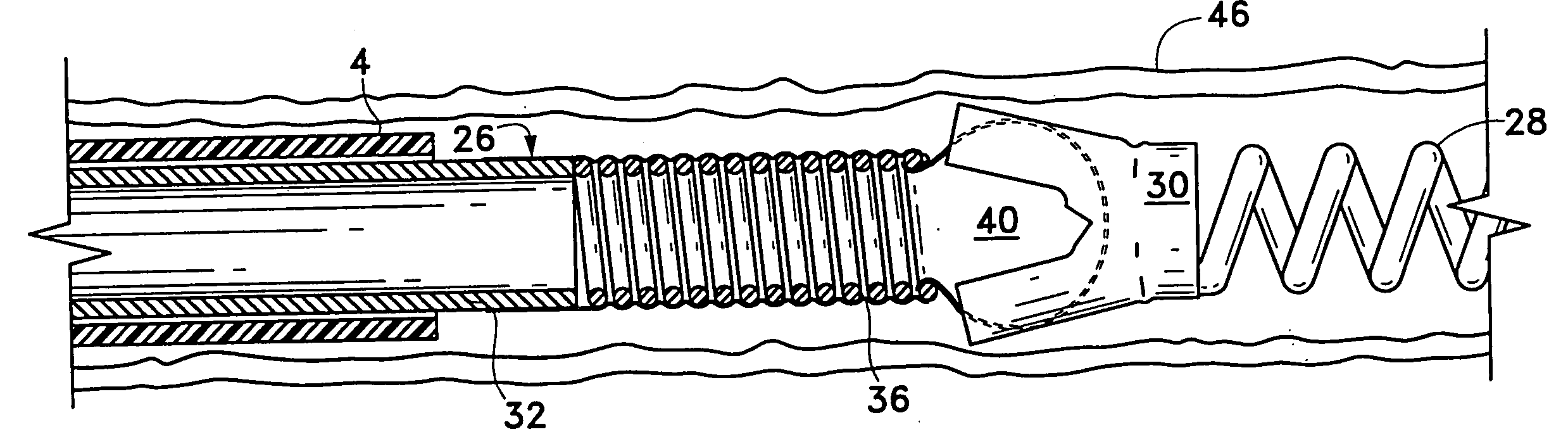
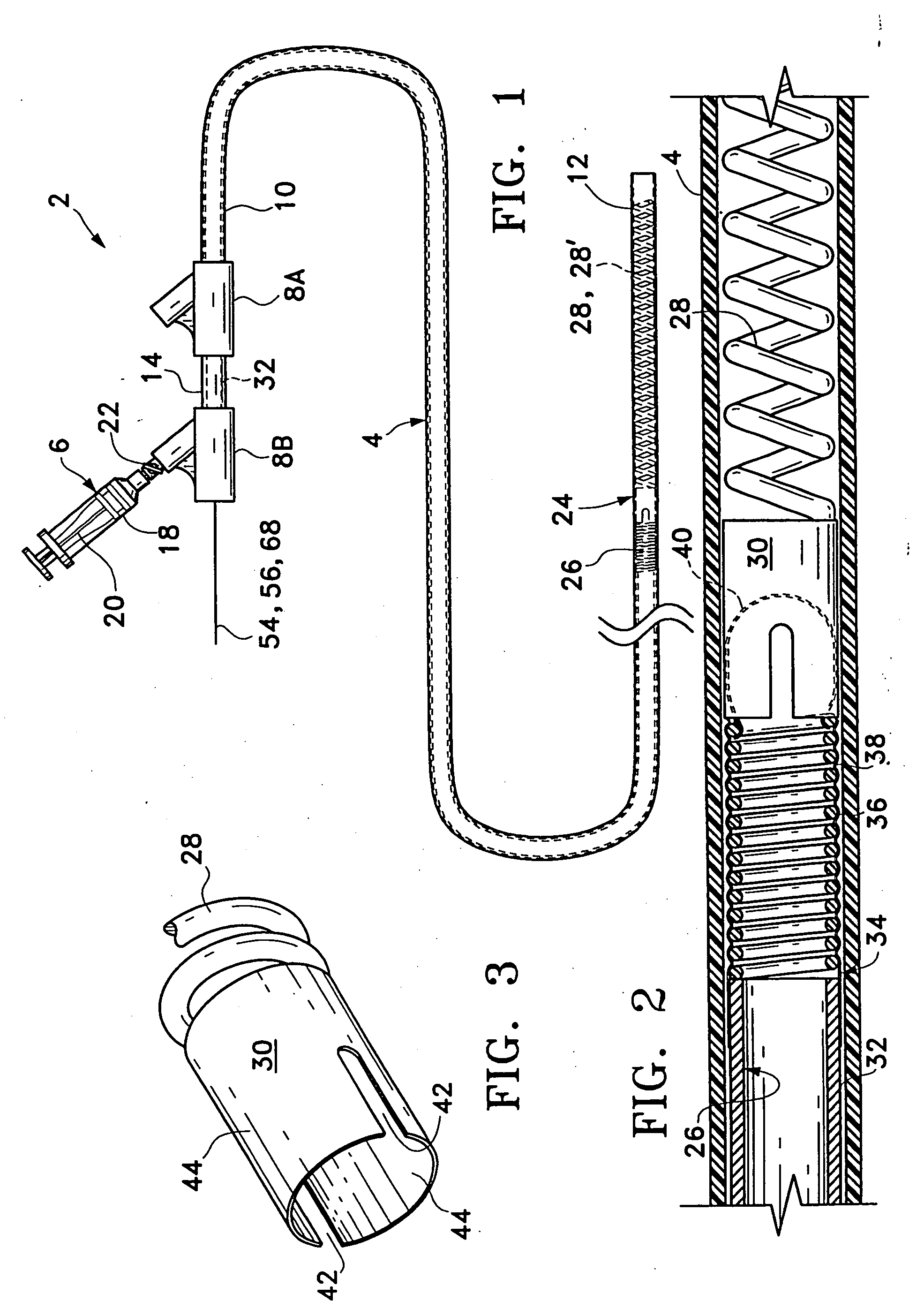
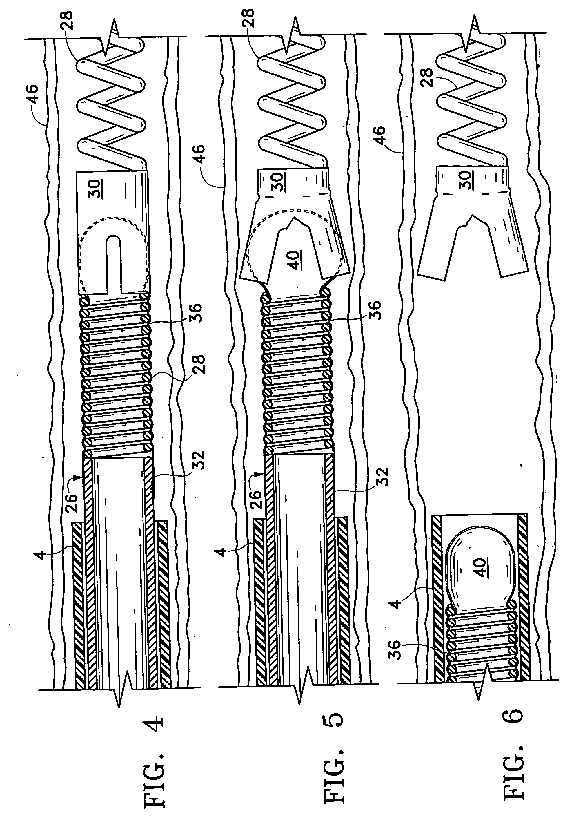
[0039] Referring to the drawings in detail, wherein like numerals indicate like elements, several embodiments of an occlusive implant delivery assembly are shown according to the principles of the present invention. The various embodiments employ an expandable mechanism, which is expanded or contracted, to decouple and release the implant at the desired site. Although variously configured implants can be used in conjunction with the assembly of the present invention, an embolic coil type implant will be described for purposes of example.

[0040] The operation of the assembly generally comprises the steps of (1) advancing a catheter through a vessel lumen, for example, to the vicinity of the site to be occluded (e.g., an aneurysm, vascular malformation, or arterial venous fistula), (2) advancing the implant delivery assembly through and beyond the catheter to the location, and (3) radially expanding or contracting the release mechanism to detach the implant from the assembly.

[0041] R...


PUM


Abstract

An occlusive implant delivery assembly includes a rapid response decoupling or detachment mechanism that does not effect significant migration of the implant during release. The assembly includes an occlusive implant device, such as an embolic coil, a pusher or device to carry the implant to the selected location, and an expandable coupling-decoupling mechanism for releasing the implant at the selected site. The mechanical construction provides rapid release times. In addition, the releasing mechanism generally operates without exerting any significant force on the implant, thereby avoiding any significant displacement of the implant during release.

Description

RELATED PATENT APPLICATION [0001] This application is a continuation of U.S. Ser. No. 08 / 363,264, filed Dec. 22, 1994, the entirety of which is hereby incorporated by reference.FIELD OF THE INVENTION [0002] The present invention generally relates to surgical instruments. More particularly, the invention relates to delivery assemblies for delivering an occlusive device, such as an embolic coil, to a selected site within a mammal using an expandable coupling or decoupling mechanism. BACKGROUND OF THE INVENTION [0003] The endovascular treatment of a variety of vascular maladies throughout the body is an increasingly more important form of therapy. Catheters have been used to place various treatment materials, devices, and drugs within arteries and veins in the human body. Examples of these devices and their use in such treatments are shown in U.S. Pat. Nos. 5,234,437 and 5,261,916, in which methods and devices for delivery of coils or wires within the human body to sites, such as aneur...

Claims


Application Information

Patent Timeline
Patent Type & Authority Applications(United States)
IPC IPC(8): A61F2/82A61B17/12A61F2/06A61F2/84
CPCA61B17/12022A61B2017/12081A61B2017/12068A61B17/1214
Inventor SEPETKA, IVANCHEE, U. HIRAM
Owner STRYKER EURO OPERATIONS HLDG LLC
Why Eureka
Try Eureka