Switching device

a technology of switching device and arc current, which is applied in the direction of relays, electrostatic generators/motors, generators/motors, etc., can solve the problems of affecting the reliability of switching characteristics, and limiting the downsizing of devices, so as to prevent damage

Inactive Publication Date: 2005-07-21
ORMON CORP
View PDF3 Cites 19 Cited by
  • Summary
  • Abstract
  • Description
  • Claims
  • Application Information

AI Technical Summary

Benefits of technology

[0017] According to the embodiment, similarly to claim 1, since the angle which can be the generation source of the arc current is formed in front of the permanent magnet, the permanent magnet can be prevented from being the generation source of the arc current and a switching device can be obtained in which the permanent magnet can be prevented from being damaged and deteriorated by the arc heat.

Problems solved by technology

In the hermetically sealed relay, however, a structure 3 for accommodating the fixed contact 22 and the movable contact disk 21 cannot be formed in compact size, and there is a limit to downsizing of the device.
This makes it difficult to assuredly shut off the generated arc current and deteriorates reliability in switching characteristic.
Further, since the generation source of the arc current 5 moves to a corner made by the permanent magnet 2 and the fixed contact terminal 1, there is a problem that the permanent magnet 2 is easily damaged and deteriorated by the arc heat.

Method used


Image

  • Switching device
  • Switching device
  • Switching device

Examples


Embodiment Construction

[0038] A preferred embodiment of the invention will be described according to the accompanying drawings of FIG. 1 to FIG. 18.

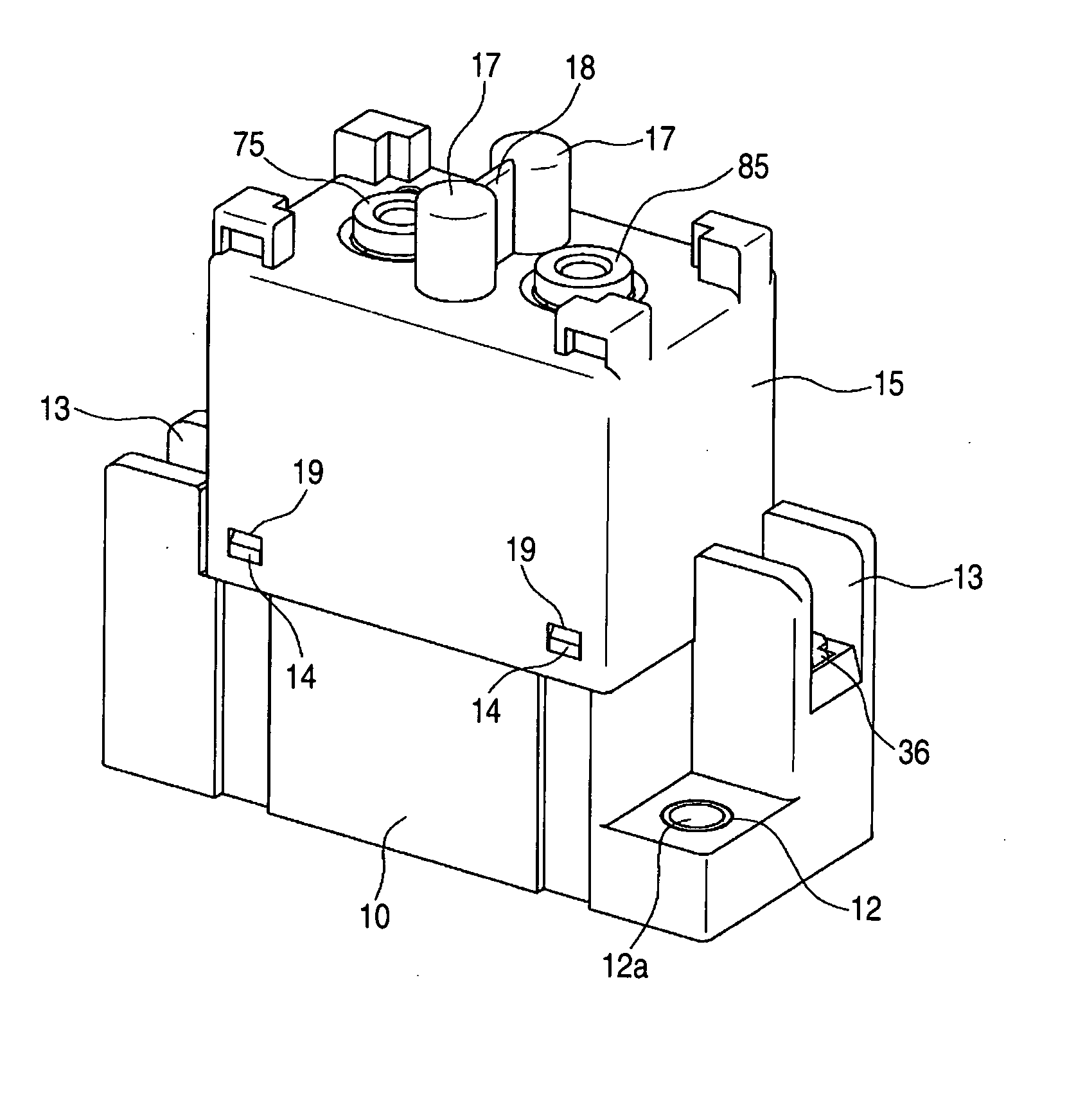
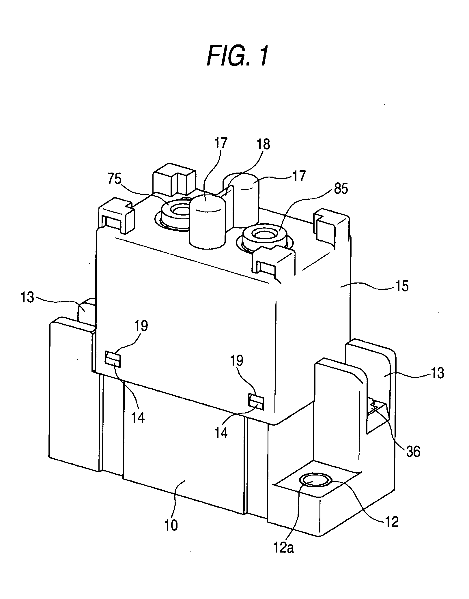
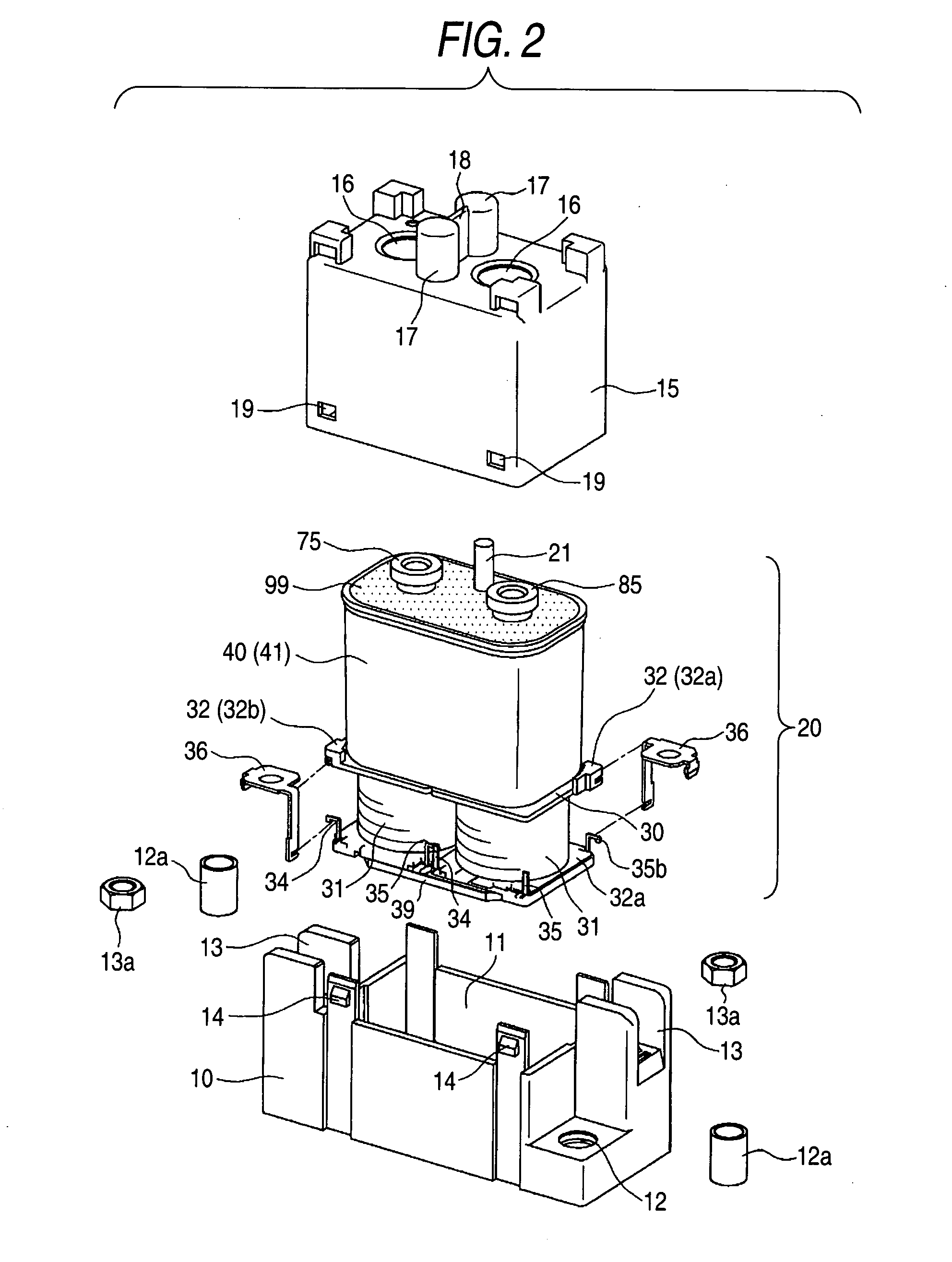
[0039] This description will be made in the case where this embodiment is used for a relay for switching a direct current load, and as illustrated in FIG. 1 and FIG. 2, the main body of a relay 20 is housed in a space integrally formed by a box case 10 and a box cover 15.

[0040] The box case 10 has a recessed portion 11 capable of housing an electromagnetic block 30 described later, and it is provided with through holes 12 for fixing respectively at two corners positioned on one of the diagonal lines and with jointing concaves 13 at the remaining two corners, as illustrated in FIG. 2. A reinforcing cylinder 12a is inserted into each of the through holes 12 and a joint nut 13a is inserted into each of the jointing concaves 13.

[0041] The box cover 15 can be fixed to the box case 10 and it has a shape capable of housing a sealing case block 40 described later. ...


PUM


Abstract

It is to provide a switching device that can be downsized and improved in reliability of the switching characteristic by making it difficult to damage and deteriorate a permanent magnet that is a component and by improving the shutoff performance. It is a switching device which makes a movable contact into/out of contact with a fixed contact, with a permanent magnet arranged in the vicinity of the fixed contact in a fixed contact terminal provided with the fixed contact on its free end. A narrow portion is formed between the fixed contact and the permanent magnet, hence to form an angle.

Description

BACKGROUND OF THE INVENTION [0001] 1. Field of the Invention [0002] The invention relates to a switching device, and more specifically to a switching device such as an electromagnetic relay, a switch, and a timer of switching currents. [0003] 2. Description of the Related Art [0004] As a switching device for breaking a direct current, there has been a hermetically sealed relay, for example, disclosed in Japanese Patent Article 1. [0005] Specifically, a plunger 9 contacts with or separates from a core center 4 according to magnetization or demagnetization of a coil 26 within a hollow cavity 40, and an armature assembly 8 and an armature shaft 10 integrated with the plunger 9 slide in a direction of the shaft, so that a movable contact disk 21 contacts with or separates from fixed contacts 22 and 22. [0006] In the above-mentioned hermetically sealed relay, the arc current generated at the time of bringing the movable contact disk 21 into / out of contact with each of the fixed contacts ...

Claims


Application Information

Patent Timeline
Patent Type & Authority Applications(United States)
IPC IPC(8): H01H9/44H01H50/00H01H50/54
CPCH01H2050/025H01H9/443
Inventor NISHIDA, TAKESHIMASUI, YASUYUKIMIYASAKA, TAKESHI
Owner ORMON CORP
Why Eureka
Try Eureka