Implantable screw for stabilization of a joint or a bone fracture

a technology for stabilizing screws and bones, applied in the field of implants for augmenting stabilization of bones, can solve the problems of severe physical impairment, inability to achieve the effect of simply suturing the capsule-ligament apparatus, and inability to withstand stress, and achieve the effect of high shaft flexibility and inadequate transferability of torsion moments

Active Publication Date: 2005-08-11
NOVOPLANT
View PDF16 Cites 107 Cited by
  • Summary
  • Abstract
  • Description
  • Claims
  • Application Information

AI Technical Summary

Benefits of technology

[0022] With a high flexibility of the shaft and therefore inadequate transferability of the torsion moments required for the thread to penetrate, it is advantageous if the implantable screw has wrench sockets in the head part as well as in the threaded part. This allows a stepped wrench to act on these wrench sockets in synchronization.

Problems solved by technology

Likewise, injuries to these joints can in many cases lead to serious physical impairments, where a painful arthrosis develops as a result of a permanent joint incongruence.
In most cases, this cannot be accomplished by simply suturing the capsule-ligament apparatus.
The sutures would not be able to withstand the stress and would rupture, and the joint would slip back into a false, incongruent position.
These implants allow good augmentation of the joint and essentially preserve mobility, but it is difficult to adjust the proper congruence of the joint, which can often be achieved only by bending the implant subsequently, because these implants do not have any suitable possibilities for adjustment.
In addition, a relatively large surgical access area is required, which necessitates a greater surgical trauma.
However, this plate has the disadvantage that it is difficult to adjust the correct congruence of the joint, and the axes of rotation of the joint and the implant do not match, so the natural movement of the joint is at least partially blocked.

Method used


Image

  • Implantable screw for stabilization of a joint or a bone fracture
  • Implantable screw for stabilization of a joint or a bone fracture
  • Implantable screw for stabilization of a joint or a bone fracture

Examples


Embodiment Construction

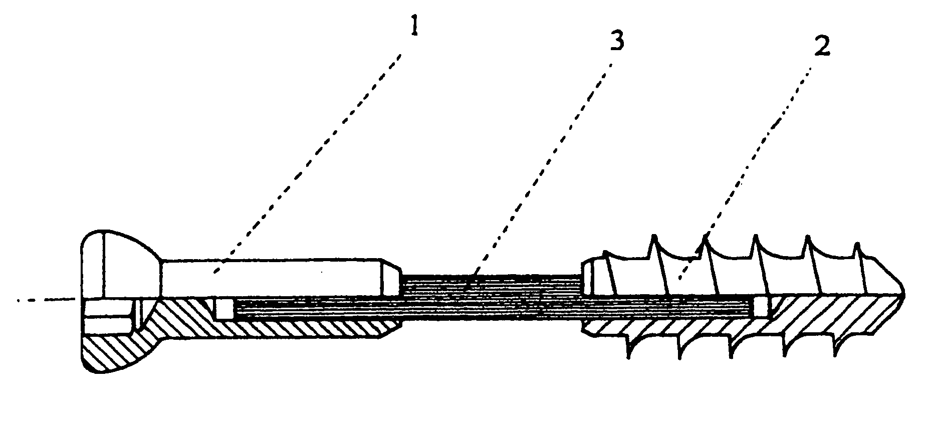
[0038] Throughout all the Figures, same or corresponding elements are generally indicated by same reference numerals.

[0039] Turning now to the drawing, and in particular to FIG. 1, there is shown a bone screw, whose head part 1 and whose threaded part 2 are flexibly interconnected by a wire cable or a wire bundle 3. The wire cable or the wire bundle is fixedly connected in the head part as well as in the threaded part through suitable connection methods (e.g., pressed, glued, soldered or welded connections). The use of a wire cable or a wire bundle allows the application of tensile forces and the transfer of torsion moments by way of a flexible shaft. Compressive forces, transverse forces or bending moments, however, are transmitted only to a slight extent.

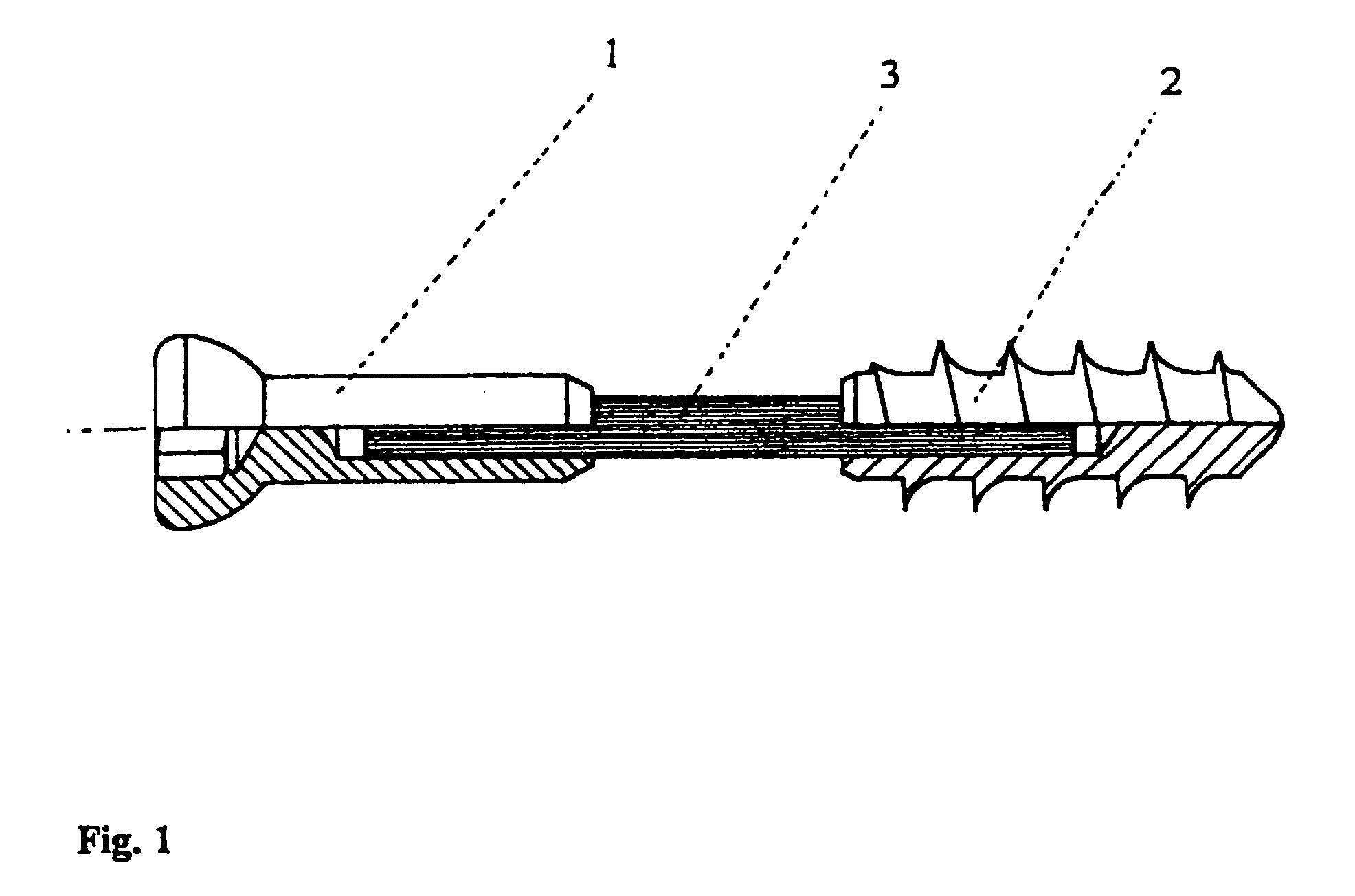
[0040]FIG. 2 shows a bone locking screw which has a head part 4, which is provided with a bone thread, and a threaded part 5, which are flexibly interconnected by a wire cable or wire bundle 6 analogeous to FIG. 1. The thread on...


PUM


Abstract

A bone screw has a flexible shaft which prevents relative movements in the direction of tension, but permits smaller movements in all other directions. The bone screw is configured as a screw insertable into medullary cavities having a curved surface, where the screw adapts to the given contour.

Description

CROSS-REFERENCES TO RELATED APPLICATIONS [0001] This application is a continuation of prior filed copending U.S. application Ser. No. 10 / 174,906, filed Jun. 18, 2002, which claims the benefit of prior filed provisional application, Appl. No. 60 / 301,267, filed Jun. 27, 2001, pursuant to 35 U.S.C. 119(e), and which claims the priority of German Patent Application Serial No. 101 29 490.5, filed Jun. 21, 2001, pursuant to 35 U.S.C. 119(a)-(d).BACKGROUND OF THE INVENTION [0002] The present invention relates in general to an implant for augmenting stabilization of bone joints and in particular to an implant for augmenting stabilization of bone joints with a low relative movement and for interfragmentary stabilization of bone fractures, when primarily tensile forces are to be applied. [0003] The joints of the body have different ranges of movement. In addition to the joints in the main axes of movement of the extremities as well as the mandibular joint, some of which have relative movement...

Claims


Application Information

Patent Timeline
Patent Type & Authority Applications(United States)
IPC IPC(8): A61B17/58A61B17/86
CPCA61B17/863A61B17/8685A61B17/866
Inventor MUCKTER, HELMUT
Owner NOVOPLANT
Why Eureka
Try Eureka