Vehicle stability control system

a technology of stability control and vehicle, applied in the direction of axle suspension, machine/engine, process and machine control, etc., can solve the problems of fluctuation of front and rear wheel ground load applied to the respective wheel, and achieve the effect of easy turning

Inactive Publication Date: 2005-09-15
DENSO CORP
View PDF40 Cites 50 Cited by
  • Summary
  • Abstract
  • Description
  • Claims
  • Application Information

AI Technical Summary

Benefits of technology

[0009] In view of the above points, the present invention has an object of suppressing the effects of driver operation disturbance or road surface disturbance to stabilize vehicle body attitude or vehicle characteristics. Another object is to ease a driving burden on a driver.
[0019] Accordingly, if a shift of the front and rear wheel ground loads generated by the pitching oscillation or the like is used to correct an axle torque generated by the engine so as to stabilize a steering characteristic governing the lateral motion of the vehicle, it is believed that the disturbance of vehicle body attitude and a vehicle characteristic can be efficiently restrained.
[0038] Therefore, the fluctuation of the behavior of the vehicle body due to the road surface or other external factors (the road surface disturbance) can be prevented from disturbing the vehicle body attitude or the running path. Since the disturbance of the attitude of the vehicle body or the vibration due to these factors is restrained, a steering operation by a driver for correcting the disturbance of the attitude of the vehicle body or the vibration is not needed any more. Therefore, a disturbance component can be prevented from being induced by the steering operation by the driver.
[0050] As described above, if the oncoming vehicle is distant from the own vehicle by the predetermined distance or more, the virtual turning radius is set so that the vehicle gives priority to the lateral translational motion rather than to the turning motion. Therefore, the own vehicle avoids the person without swerving, that is, moves as if the own vehicle laterally slid when it is viewed from the oncoming vehicle. Therefore, the own vehicle does not seem to stray onto the opposite lane. Accordingly, the driver of the oncoming vehicle can be less intimidated.
[0053] As described above, when the vehicle speed is higher than the predetermined speed and the vehicle is running at high speed, the virtual turning radius is set so that the vehicle gives priority to the lateral translational motion to the turning motion. Therefore, during high-speed running, the vehicle does not turn so as to laterally move the nose to make a lane change, but the vehicle makes a lane change as if the vehicle laterally slid. Therefore, more sense of the security can be given to the driver.
[0054] Moreover, when the vehicle is running at low speed that is lower than the predetermined speed, the virtual turning radius is set so that the vehicle gives priority to the turning motion rather than the lateral translational motion. Therefore, during low-speed running, the vehicle can turn sharply, giving an impression that the vehicle is easy to turn to the driver.

Problems solved by technology

As a result, front and rear wheel ground loads applied to the respective wheels are fluctuated by the above-described driver operation disturbance or road surface disturbance.

Method used


Image

  • Vehicle stability control system
  • Vehicle stability control system
  • Vehicle stability control system

Examples


Embodiment Construction

[0078] Hereinafter, the embodiments of the present invention will be described based on the drawings. In each of the following embodiments, the same or equivalent parts are denoted by the same reference numerals in the drawings.

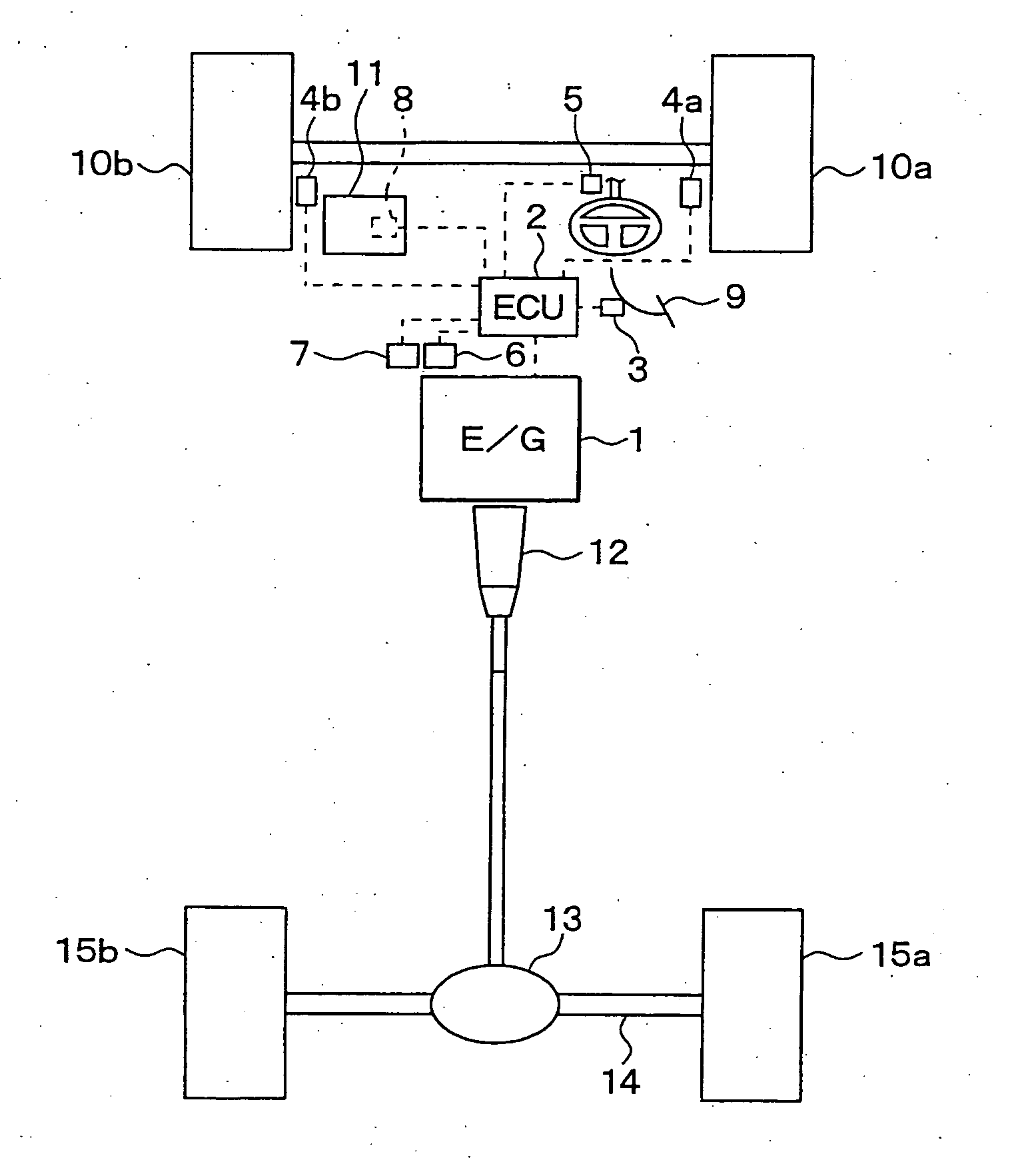
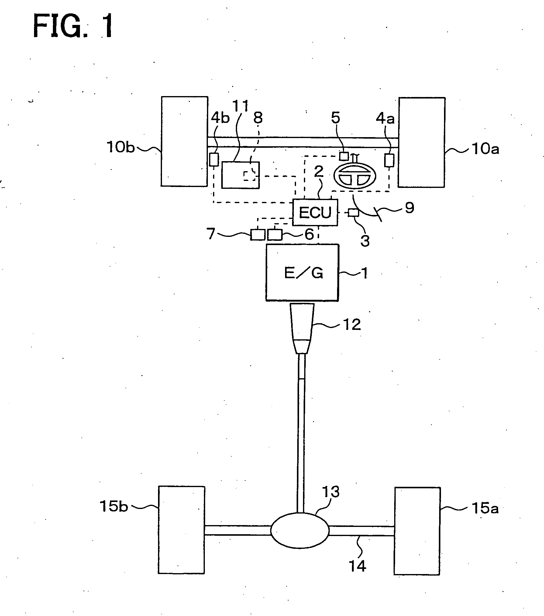
[0079] A vehicle stability control system of one embodiment of the present invention will be described. FIG. 1 shows a schematic structure of a vehicle stability control system in this embodiment. Although the description will be given assuming a driving mode of a vehicle is rear wheel drive in this embodiment, it is apparent that the present invention can be applied even to a front wheel drive vehicle and a four-wheel drive vehicle.

[0080] The vehicle stability control system in this embodiment adjusts a driving torque generated by an engine 1 provided for a vehicle so as to stabilize a fluctuation of a stability factor based on a shift of front and rear wheel loads due to pitching oscillation energy or the like, thereby stabilizing the attitude of a vehicl...


PUM


Abstract

A vehicle stability control system includes a basic request driving force computing unit, a front and rear wheel load computing unit, a virtual turning radius estimating unit, a target value computing unit, and a vibration damping correction controlling unit. The basic request driving force computing unit computes a physical quantity so as to generate the basic request driving force requested by a driver. The front and rear wheel load computing unit detect a load applied to the wheels. The virtual turning radius estimating unit estimates a virtual turning radius. The target value computing unit computes a target value of a stability factor. The vibration damping correction controlling unit corrects the physical quantity so as to follow the target value. The system generates the driving force for the driving wheel.

Description

CROSS REFERENCE TO RELATED APPLICATIONS [0001] This application is based upon and claims the benefit of priority of Japanese Patent Application No. 2004-65927, filed on Mar. 9, 2004, the contents of which are incorporated herein by reference. FIELD OF THE INVENTION [0002] The present invention relates to a vehicle stability control system and a vehicle stability control method for controlling a change in cornering power due to a change in ground load of each of front and rear wheels so as to stabilize the running of a vehicle. BACKGROUND OF THE INVENTION [0003] Conventionally, in vehicle running control, lane maintenance control for controlling a vehicle so as to ensure the running of the vehicle in a lane indicated with a white line or the like is known. An example of such a control is disclosed in Japanese Patent Laid-Open Publication No.2000-168599. [0004] In the lane maintenance control, a white line drawn on a running road surface is recognized by a vehicle-mounted camera or th...

Claims


Application Information

Patent Timeline
Patent Type & Authority Applications(United States)
IPC IPC(8): B60K28/16B60R1/00B60K31/00B60W10/04B60W10/06B60W10/20B60W30/00B60W30/02B60W30/045B62D6/00B62D101/00B62D109/00B62D113/00B62D127/00B62D131/00B62D133/00B62D137/00F02D29/02F02D45/00
CPCB60W10/04B60W2510/20B60W30/045
Inventor SAWADA, MAMORUMATSUMOTO, TOSHIKI
Owner DENSO CORP
Why Eureka
Try Eureka