Power converter circuit and associated triggering method for generators with dynamically variable power output

a technology of power converter circuit and generator, applied in the direction of dynamo-electric converter control, electric generator control, instruments, etc., can solve the problems of power converter circuit, favorable, robust, and inability to use asynchronous machines with such circuits, and achieve the effect of improving the efficiency of asynchronous machines and reducing the complexity of circuitry

Inactive Publication Date: 2005-09-15
SEMIKRON ELECTRONICS GMBH & CO KG
View PDF10 Cites 41 Cited by
  • Summary
  • Abstract
  • Description
  • Claims
  • Application Information

AI Technical Summary

Problems solved by technology

Power converter circuits of this kind, however, suffer from a drawback, namely, that favorable, robust, asynchronous machines cannot be used with such circuits, since they require a magnetic rotating field for their excitation.
Another disadvantage of such circuits is the relatively high complexity of circuitry, which, for example, precludes installing a circuit of this kind into existing wind power systems, for economic reasons at least.
However, such a simple circuit has several disadvantages.
At low wind speeds, because the generator speed is kept constant, coupling to the electrical network is possible, if at all, only with highly restricted efficiency, because of the inadequate output power.
Moreover, with this circuit arrangement, a reactive power compensation that the applicable energy supply business requires cannot be attained in every operating state.
A wind power system of the construction described above, with direct coupling of the generator to the electrical network, cannot meet this precondition.

Method used


Image

  • Power converter circuit and associated triggering method for generators with dynamically variable power output
  • Power converter circuit and associated triggering method for generators with dynamically variable power output

Examples


Embodiment Construction

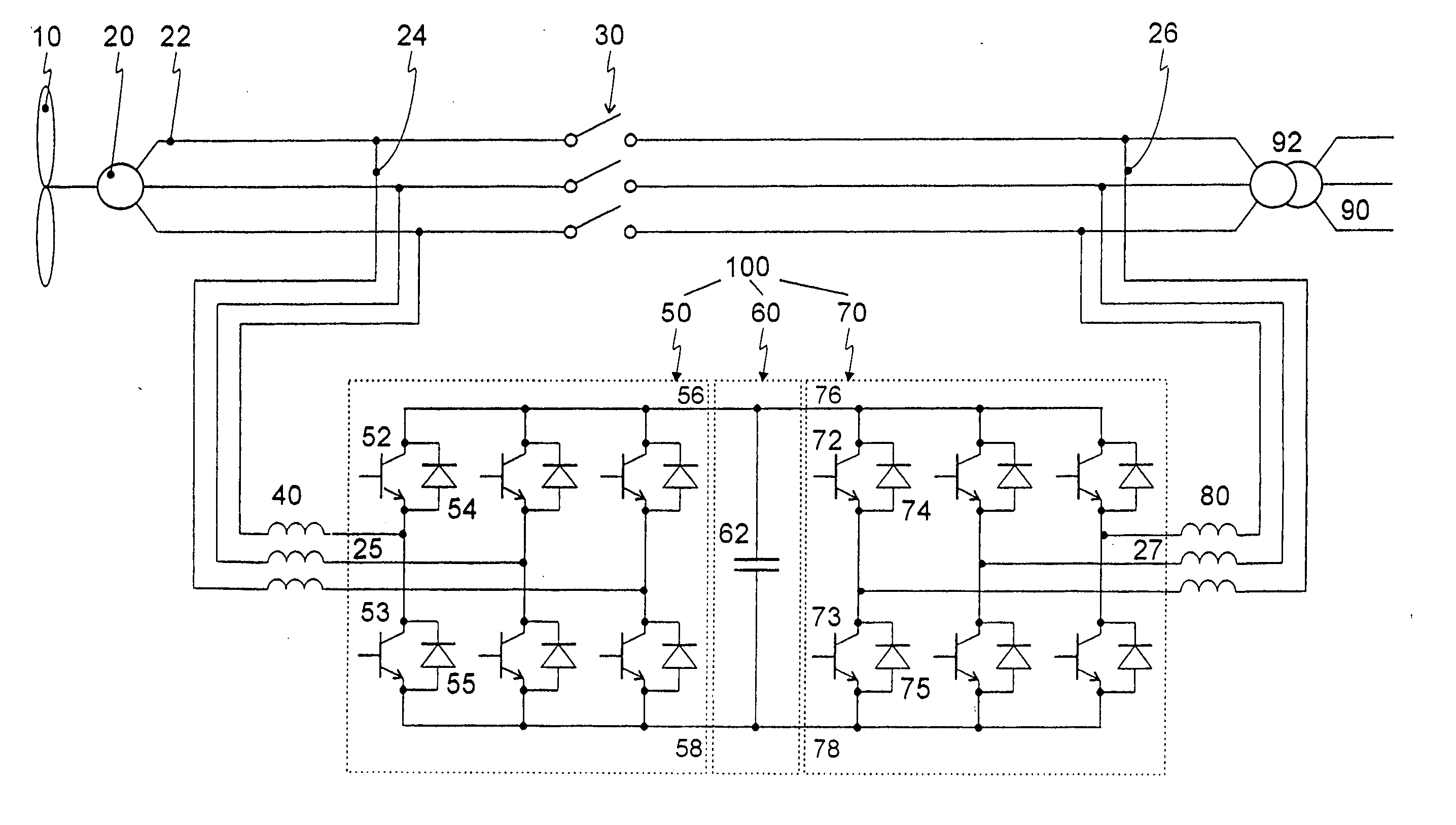
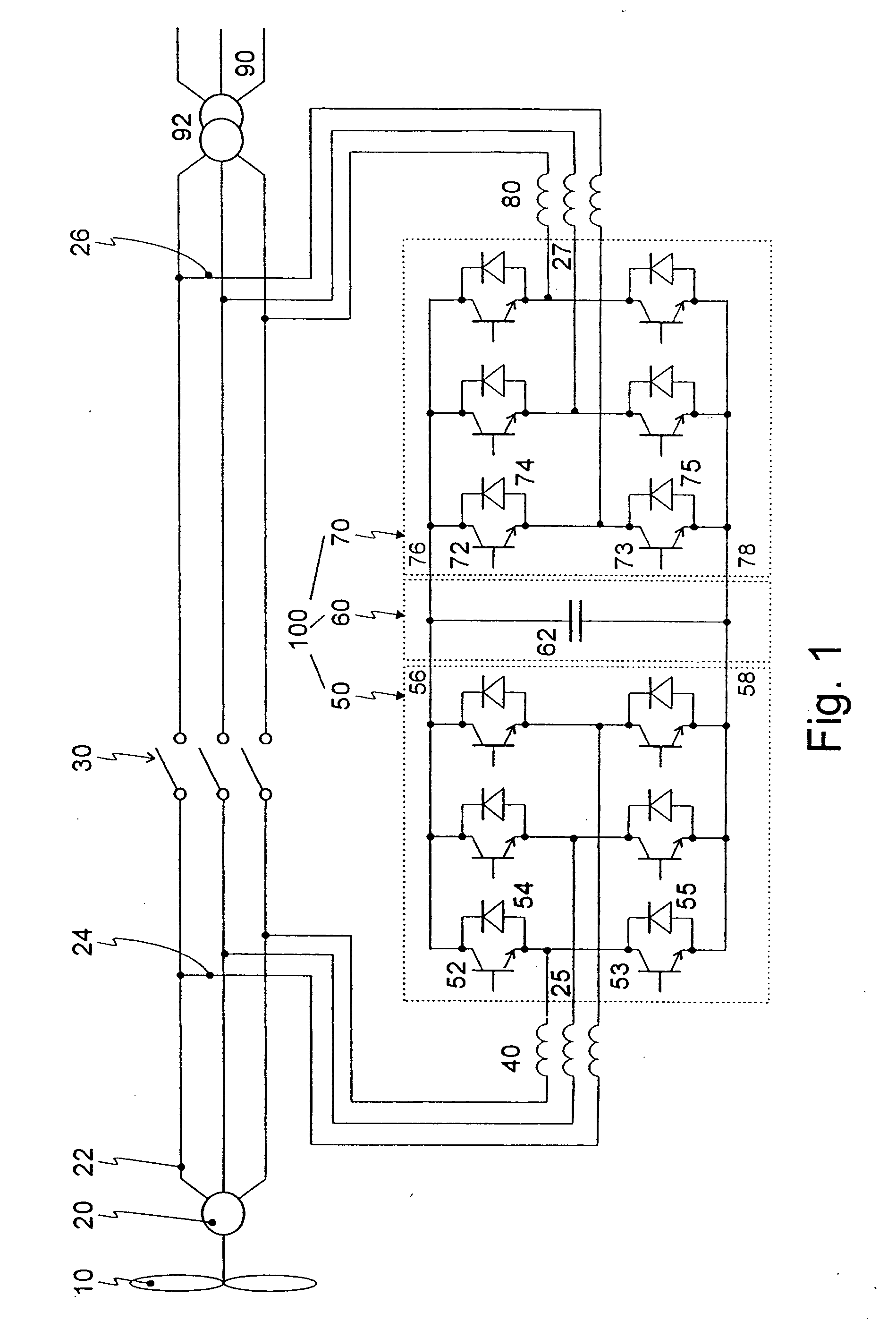
[0019] A wind power system is shown in FIG. 1, with a rotor 10 which drives a generator 20 via a gear. Generator 20 is an asynchronous machine, with a rated output voltage of 690 V in accordance with the prior art, and has three output phases 22 which are connected to a medium-voltage electrical network 90 via a transformer 92. To this extent, what is shown corresponds to the prior art of the kind already in frequent use as a wind power system.

[0020] For inexpensive expansion of an existing wind power system, or for producing a new, inexpensive wind power system, the circuit shown is expanded in an inventive way with a power converter circuit. This power converter circuit is designed as a four-quadrant converter 100 and comprises one power converter 50, for generator 20 and one power converter 70 for the network 90. Each power converter 50, 70 in turn comprises three half-bridge circuits. These half-bridge circuits in turn each comprise one upper power semiconductor switch 52, 72 a...


PUM


Abstract

A power converter circuit and associated triggering method for connecting a three-phase generator to an electrical network. The circuit includes a first direct connection of the generator to the network and a second connection of the generator to the network, through a four-quadrant converter which includes a first power converter, whose alternating voltage terminals are connected to the generator, and a second power converter, whose alternating voltage terminals are connected to the network. The triggering method for power compensation in the event of a short circuit is such that in a first period of time after the short, the second power converter outputs reactive power into the network; in a second period of time, the power converter feeds reactive power back into the network; and in a third period of time, the entire four-quadrant converter controls the gentle restarting, without loading the network with reactive power from the generator.

Description

BACKGROUND OF THE INVENTION [0001] 1. Field of the Invention [0002] The invention is directed to a power converter circuit for connecting a three-phase generator to an electrical network. Such circuits are used for instance in a wind power system. In that case, a dynamically varying output power of the generator is self-evident because of natural conditions, that is, due to varying wind speeds. [0003] 2. Description of the Related Art [0004] The current generated in a generator must be fed into an existing electrical network in a way that is appropriate for the network in terms of voltage, frequency and phase. Typical magnitudes of voltages in such networks range from a few hundred to several tens of kilovolts and frequencies of 50 Hz or 60 Hz. [0005] Prior art wind power systems which vary dynamically over time and include the following technologies. [0006] German Patent Disclosure DE 101 14 075 A1 discloses a complex connection of a generator having a dynamic power output to a med...

Claims


Application Information

Patent Timeline
Patent Type & Authority Applications(United States)
IPC IPC(8): H02J3/18H02J3/38H02M5/458
CPCH02J3/1842H02J2003/001Y02E10/763Y02E40/22H02J3/386H02M5/4585H02J3/001H02J2300/28H02J3/381Y02E10/76Y02E40/20
Inventor SCHREIBER, DEJANHEILBRONNER, HEINRICH
Owner SEMIKRON ELECTRONICS GMBH & CO KG
Why Eureka
Try Eureka