

Power amplifier
a power amplifier and pulse width technology, applied in dc amplifiers with modulator-demodulator only, amplifiers with semiconductor devices, dc amplifiers with modulator-demodulator, etc., can solve the problems of 4 not being able to provide the minimum and maximum power amplifier output at a desired ratio, and the speaker may be broken (burnt out), so as to achieve the effect of novel power amplifiers
- Summary
- Abstract
- Description
- Claims
- Application Information
AI Technical Summary
Benefits of technology
Problems solved by technology
Method used
Image

Examples
Embodiment Construction
[0055] The present invention will be described concerning embodiments in which the present invention is applied in the aforementioned digital audio signal power amplifier.
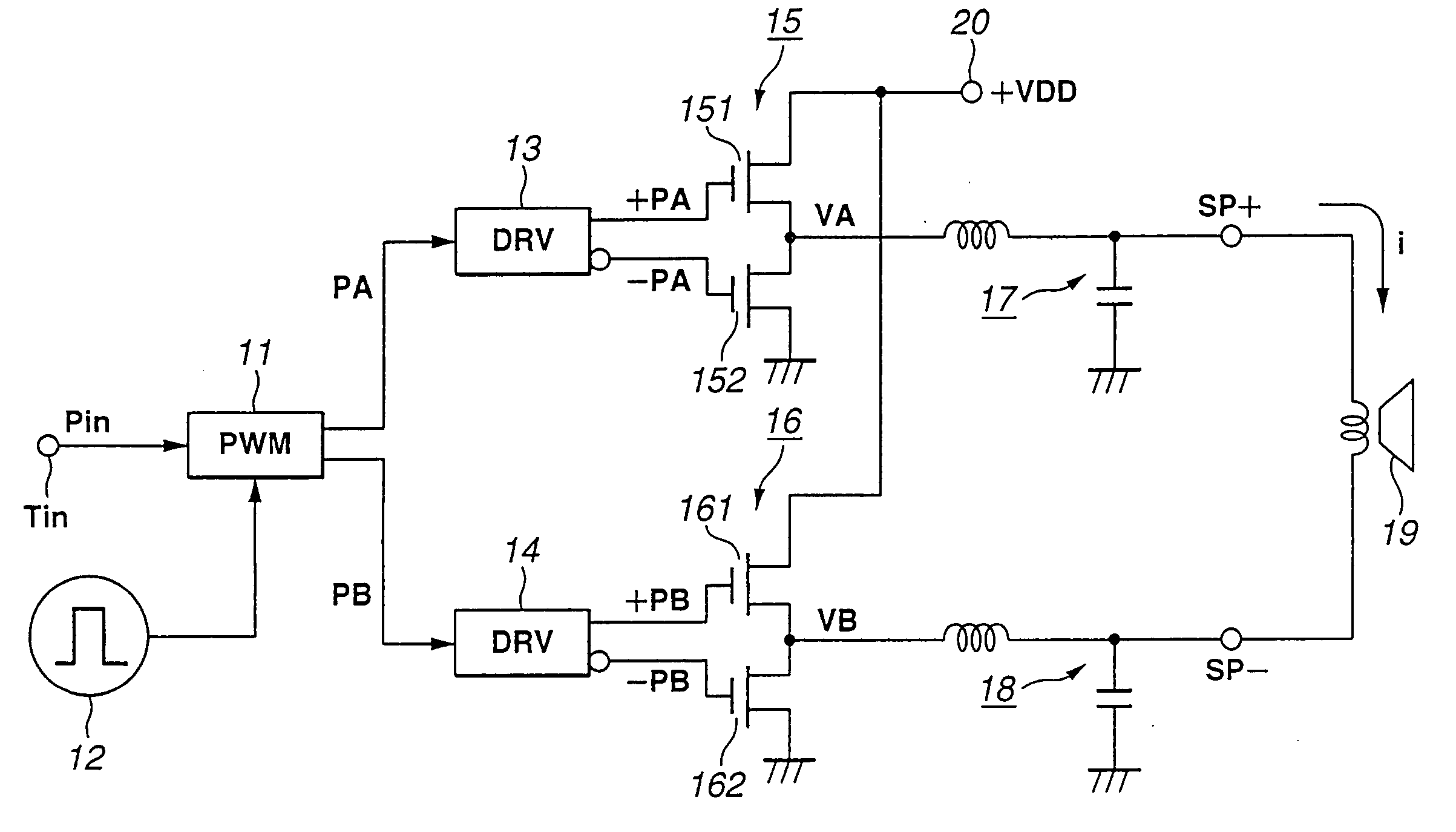
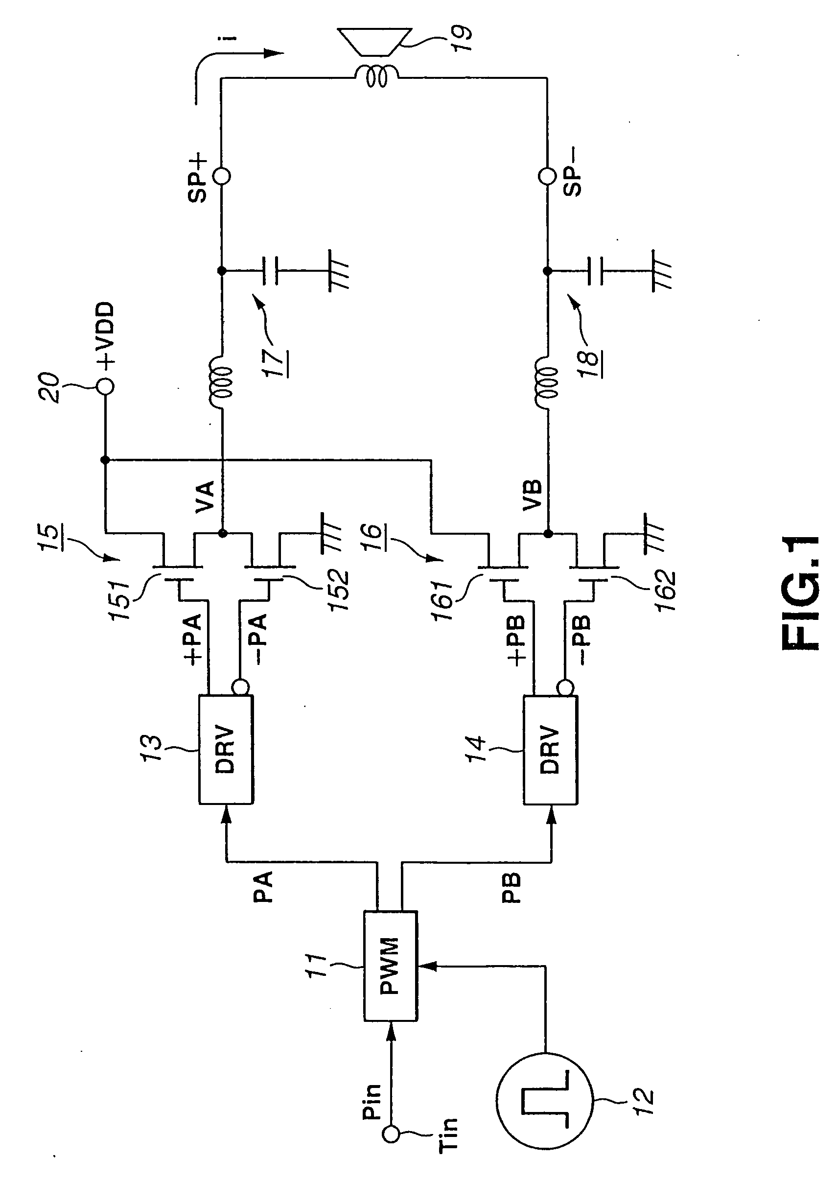
[0056]FIG. 5 is a circuit diagram of the power amplifier according to the present invention, showing the construction of the latter. The PWM-driven circuit part except for the overcurrent detection circuit part is quite the same as in FIG. 1.
[0057] In the power amplifier according to the present invention, a source voltage +VDD from a power terminal 20 is supplied, not via any resistor but directly, to push-pull circuits 15 and 16, differently from the conventional power amplifier having been described with reference to FIG. 4.
[0058] As shown, the overcurrent detection circuit, generally indicated with a reference 30, included in the power amplifier according to the present invention includes push-pull circuits 15 and 16 and a series circuit from resistors 31, 32 and 33 connected between a junction TP 15 between...
PUM
 Abstract
Description
Claims
Application Information