Compact contact lens case with time tracking device

a technology of time tracking and contact lens case, which is applied in the direction of packaging, other accessories, trays, etc., can solve the problems of cumbersome contact lens case and less accessible to the contact lens wearer

Inactive Publication Date: 2005-11-24
SIEG PHIL
View PDF7 Cites 23 Cited by
  • Summary
  • Abstract
  • Description
  • Claims
  • Application Information

AI Technical Summary

Problems solved by technology

Another problem with existing compact lens cases with time tracking devices is that they presume that the compact lens wearer will wear the left and right contact lenses beginning on different dates and therefore require the compac

Method used


Image

  • Compact contact lens case with time tracking device
  • Compact contact lens case with time tracking device
  • Compact contact lens case with time tracking device

Examples


Embodiment Construction

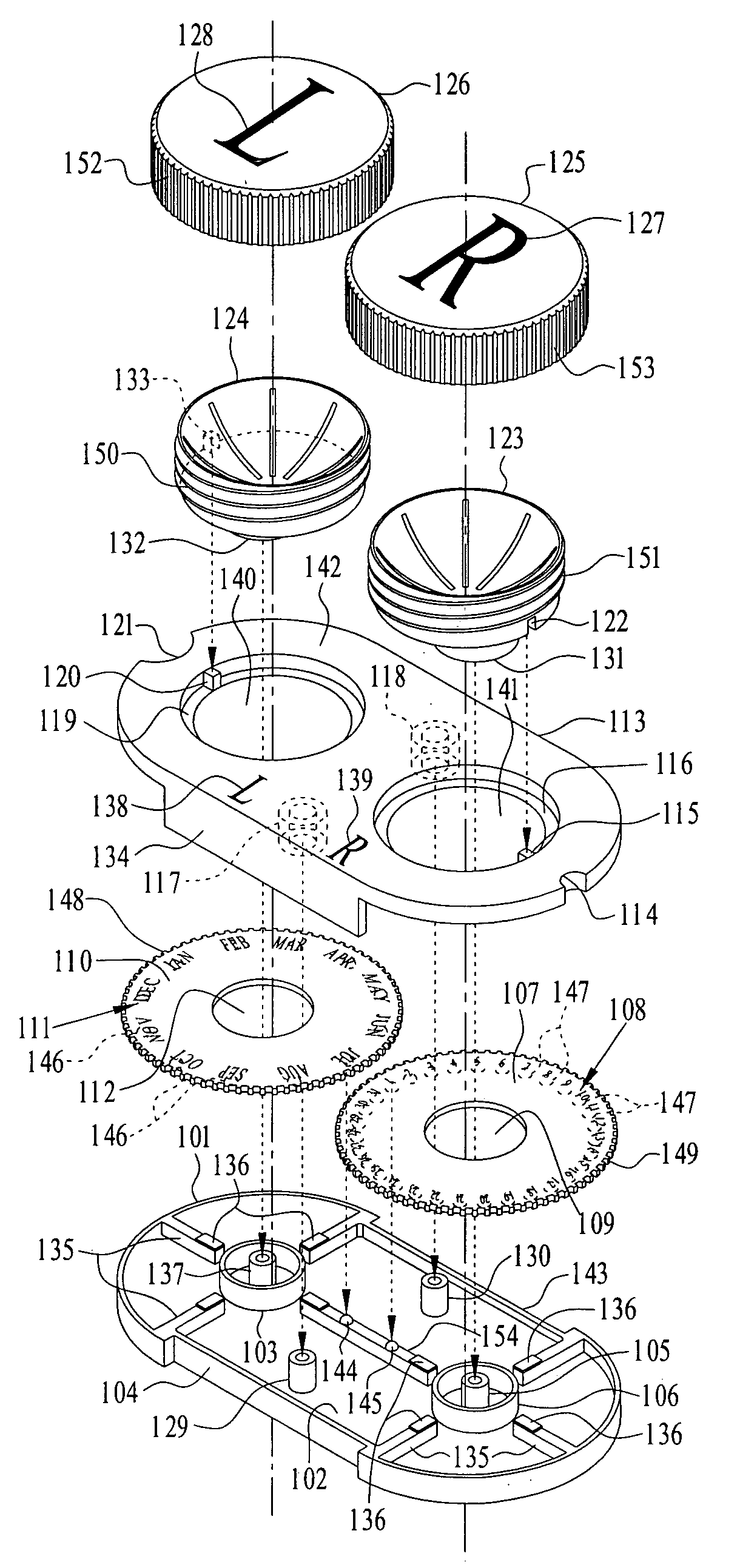
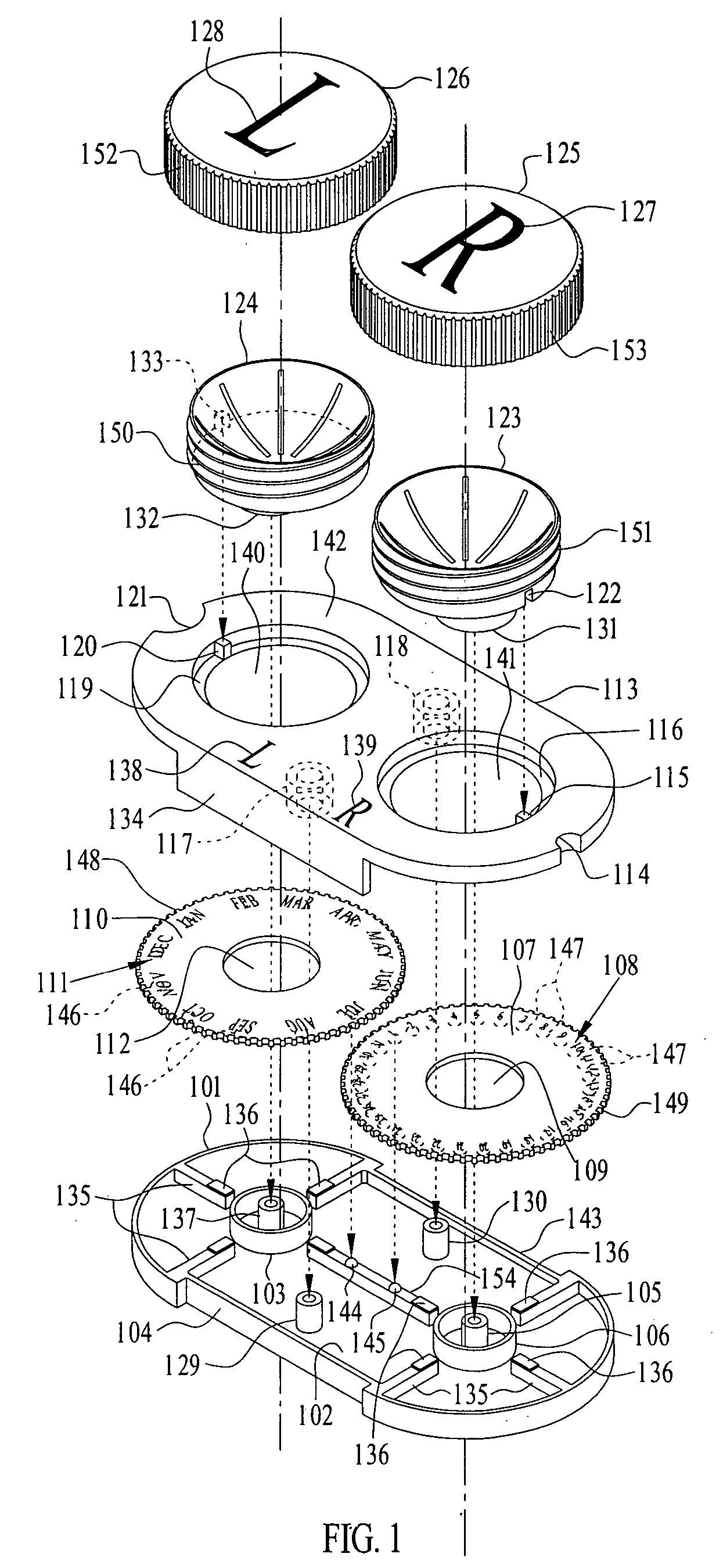
[0029] Referring to FIG. 1 there is shown a perspective view of a first preferred embodiment of the present invention.

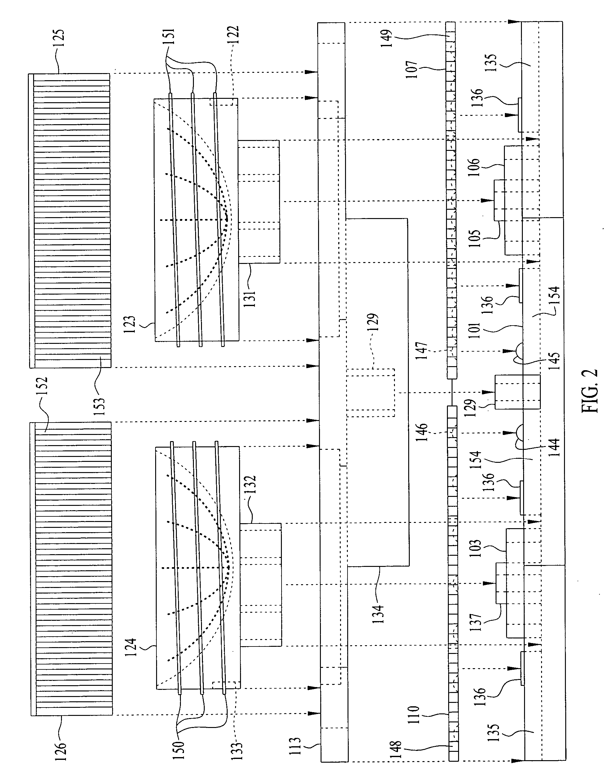
[0030] In a first preferred embodiment of the present invention there is provided a compact contact lens case, preferably of plastic, comprising a base 101 having a top side 102 with a top member 113 positioned on the top side 102 of the base 101. Attached to the top side 102 of the base 101 are mounting beams 135 and 154 with mounting ledges 136 on each of mounting beams 135 and 154. Attached to the top of mounting beam 154 are left knob 144 and right knob 145. Attached to the top side 102 of the base 101 are connecting posts 129 and 130, also seen in FIG. 10. Referring now to FIGS. 1 and 7 it is seen that the base 101 has a front indent 104 that receives a front flap 134 protruding from the top member 113 when the compact contact lens case of the present invention is assembled. The base 101 has a rear indent 143 that receives a rear flap 901 shown in FIG. 9, a bot...


PUM


Abstract

A compact contact lens case with a base having a top side, a top member with a right opening that receives a right receptacle for receiving a right contact lens, and with a left opening for receiving a left receptacle for receiving a left contact lens and positioned on the top side of said base, a right side receptacle for receiving a right contact lens, a left side receptacle for receiving a left contact lens, a cover for the right side receptacle for receiving a contact lens, a cover for the left side receptacle for receiving a contact lens, and a date wheel for indicating a date related to use of the contact lenses that is manually adjustable independently of a month wheel for indicating a date related to use of the contact lenses. The month wheel is manually adjustable independently of the setting of the date wheel.

Description

CROSS-REFERENCES TO RELATED APPLICATIONS [0001] This application claims the benefit of Provisional Application No. 60 / 561,175 filed Apr. 8, 2004. The prior application is hereby incorporated herein by reference as though fully set forth herein.STATEMENT REGARDING FEDERALLY SPONSORED RESEARCH OR DEVELOPMENT [0002] Not Applicable. REFERENCE TO A MICROFICHE APPENDIX [0003] Not Applicable. BACKGROUND OF THE INVENTION [0004] 1. Field of the Invention [0005] The present invention relates generally to contact lens cases with time tracking devices. [0006] 2. Description of the Related Art [0007] The closest prior art of which applicant is aware is U.S. Pat. No. 6,382, 409 issued to Scala, “Contact Lens Case with Time Tracking Structure.”[0008] The Contact Lens Case with Time Tracking Structure comprises a base having a top side, left side and right side cups positioned on the top side of the base which respectively receive a contact lens, a timing mechanism on the left side for indicating a...

Claims


Application Information

Patent Timeline
IPC IPC(8): A45C11/00A45C11/04B65D85/00
CPCA45C11/005
Inventor SIEG, PHIL
Owner SIEG PHIL
Why Eureka
Try Eureka