Crossbar spinal prosthesis having a modular design and related implantation methods
Inactive Publication Date: 2005-11-24
FACET SOLUTIONS
View PDF63 Cites 196 Cited by
Summary
Abstract
Description
Claims
Application Information
AI Technical Summary
This helps you quickly interpret patents by identifying the three key elements:
Problems solved by technology
Method used
Benefits of technology
Benefits of technology
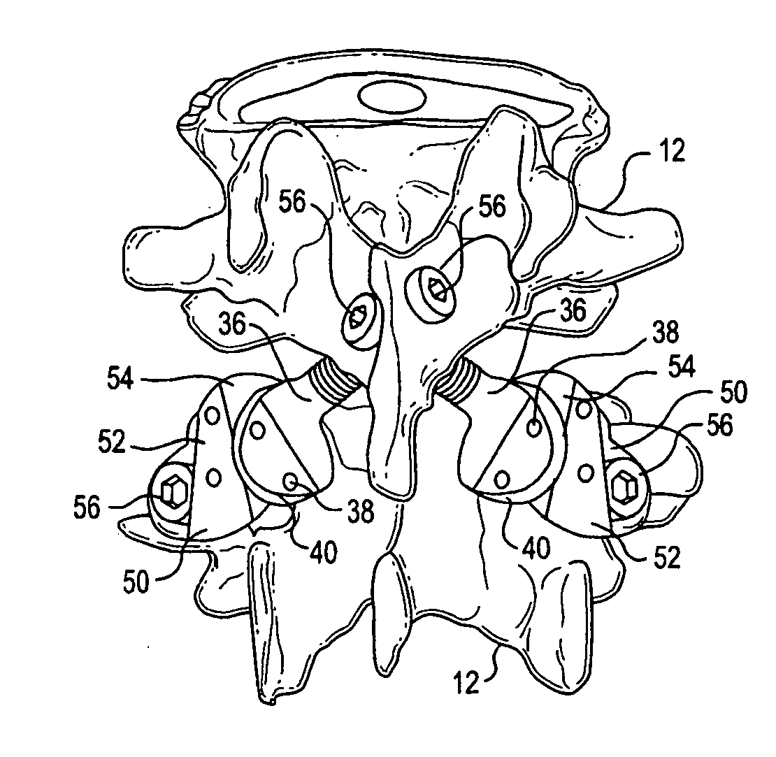
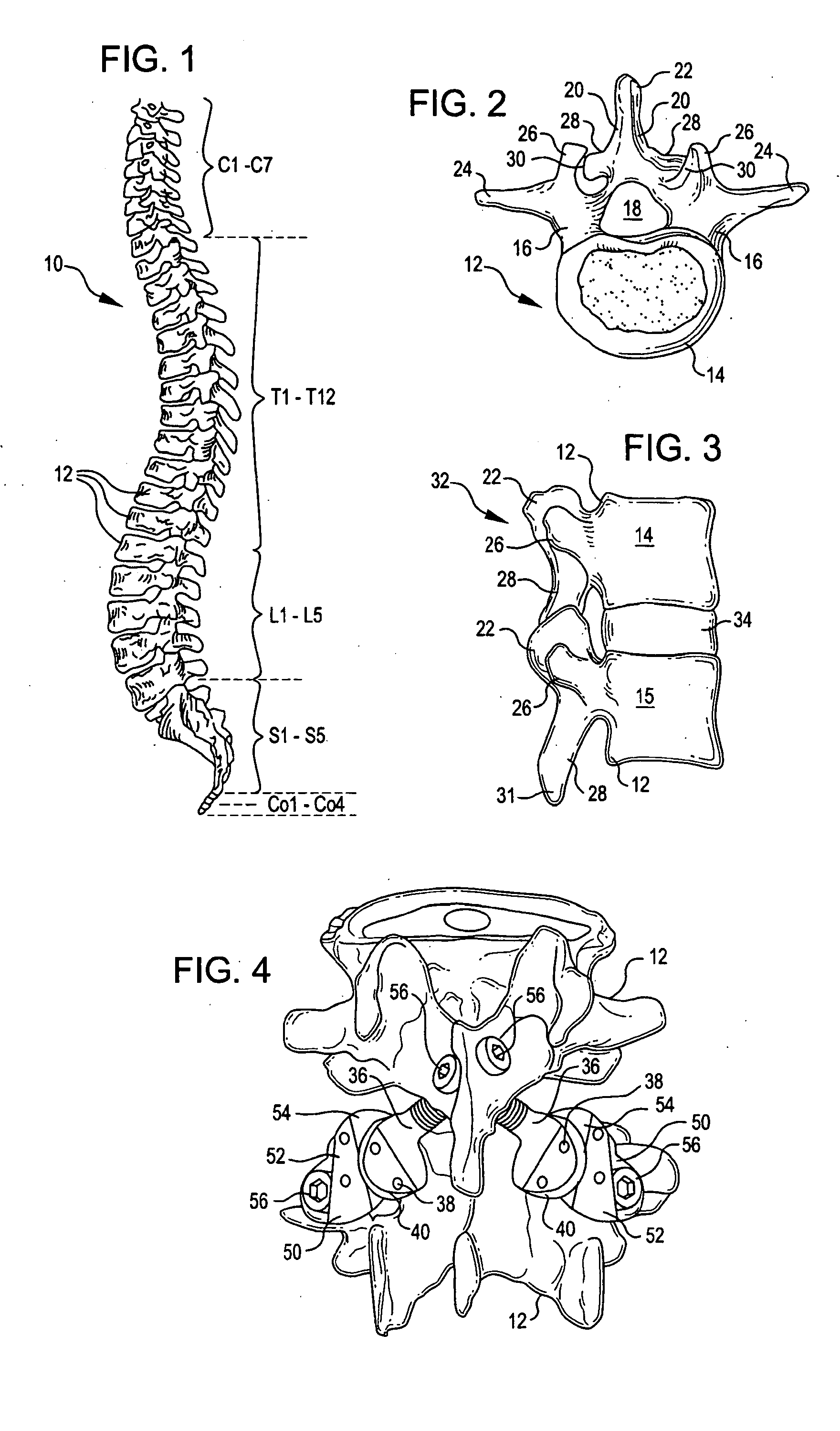
[0016] Prostheses, systems and methods exist which can maintain more spinal biomechanical functionality than the above discussed methods and systems and overcome many of the problems and disadvantages associated with traditional treatments for spine pathologies. One example of such prosthesis is shown in FIG. 4. FIG. 4 shows an artificial cephalad and caudal facet joint prosthesis 36 and 50 for replacing a natural facet joint. Cephalad joint prosthesis 36replaces the inferior facet of a natural facet joint. Cephalad prosthesis 36 has a bearing
Problems solved by technology
Prosthesis customization to patient specific disease state and anatomy are among the challenges faced when implanting a prosthesis.
Current prostheses
Method used
Image
Click on the blue label to locate the original text in one second.
Reading with bidirectional positioning of images and text.
Examples
first embodiment
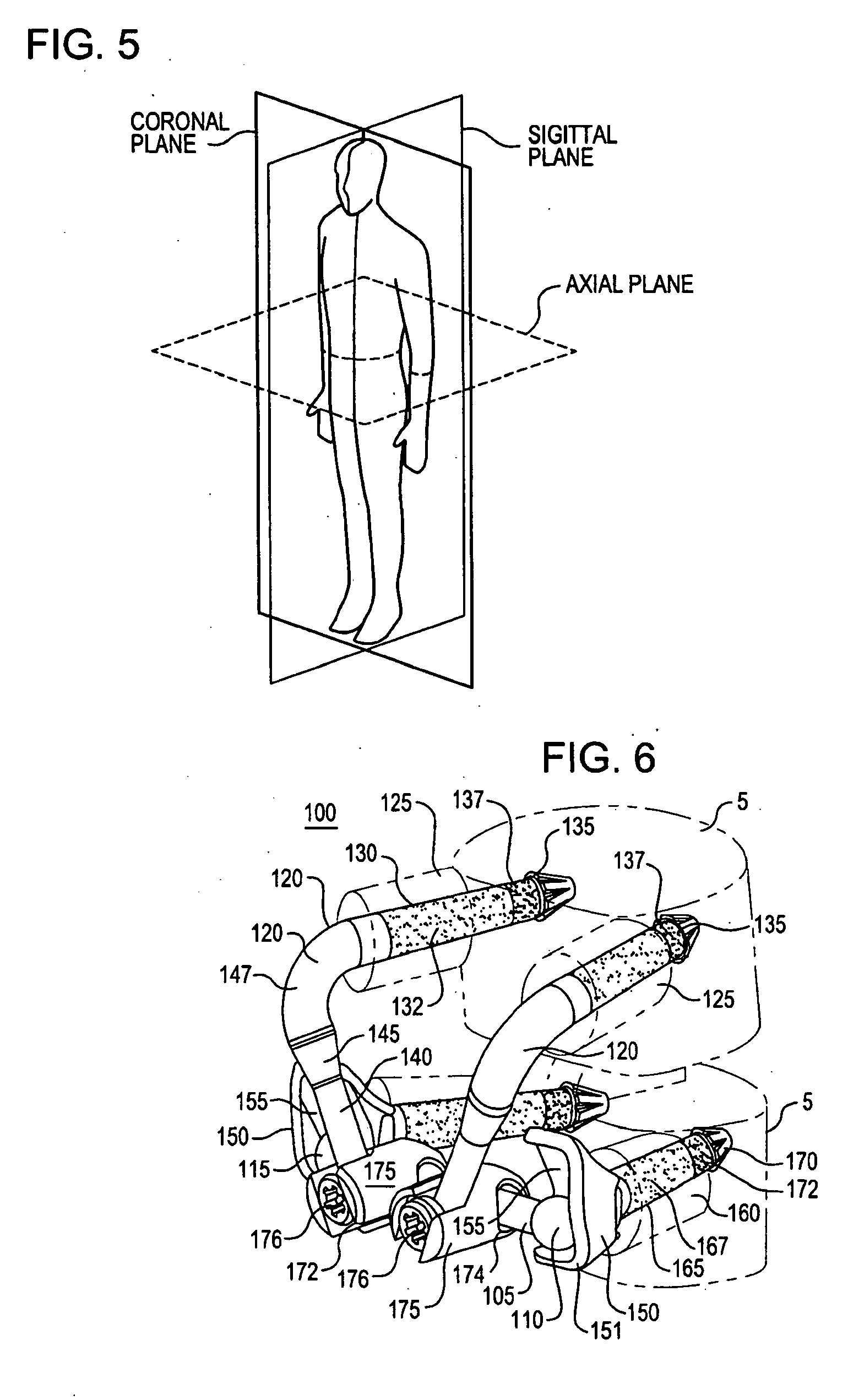
[0080] The crossbar 105, in a first embodiment, has a first end 110 and a second end 115. In the illustrated embodiment the crossbar 105 is a two piece bar where the first end 110 is attached to a threaded male portion 104 having threads 109. The crossbar second end 115 is attached to a threaded female portion 106 sized to receive the threads 109. As will be described in greater detail below, the threaded ends allow for the width of the crossbar to be adjusted to mate with the width between caudal bearings 150 (FIG. 9). Additional alternative embodiments of the crossbar 105 could include a series of solid crossbars of varying widths and / or thicknesses (See FIGS. 9A, 9B and 9C), or an-adjustable crossbar having some form of locking or biasing mechanism (such as a spring-loaded tensioner or detent mechanism, etc.).
[0081] A pair of cephalad prosthesis elements 120 are also illustrated in the exemplary embodiment of the configurable and adaptable spinal prosthesis 100 of the present inv...
embodiment 330
[0192]FIG. 31C illustrates an embodiment of an adaptive spinal prosthesis 300C having a crossbar embodiment 330 and crossbar locks 331. A crossbar lock 331 includes a cephalad arm clamp 334 about a cephalad arm 145 and a crossbar clamp 336 that encircles the crossbar 330. A dual clamp housing 332 and fastener 338 join the clamps 334, 336. The width of crossbar 330 is determined by moving the crossbar 330 relative to the crossbar clamps 336. The crossbar spacing between a cephalad bearing 305 and an elbow 147 is determined by moving the cephalad arm clamp 334 along the cephalad arm 147 to the desired position. Once the width of crossbar 330 and the position of the crossbar 330 relative to the bearing 305 and the elbow 147 are selected, the crossbar 330 is secured into the selected position by tightening the fastener 338. Tightening fastener 338 results in articulation within dual clamp housing 332 to tighten both the arm clamp 334 about the cephalad arm 145 and the crossbar clamp 336...
embodiment 340
[0193]FIG. 31D illustrates an embodiment of an adaptive spinal prosthesis 300D having a crossbar embodiment 340 with crossbar locks 341. A crossbar lock 341 includes a cephalad arm clamp 342, a crossbar clamp 344 and a fastener 346. The position of the crossbar 340 between the cephalad bearing 305 and the elbow 147 is changed by sliding the arm clamps 342 along the cephalad arms 147. The crossbar width between the crossbar clamps 344 is adjusted by sliding the crossbar 344 relative to the clamps 344. Once the position of the crossbar 340 between the cephalad bearing 305 and the elbow 147 and the width of the crossbar 340 are selected, the crossbar position is secured by tightening fastener 346. Tightening fastener 346 urges the arm clamp 342 about the cephalad arm 145 and the crossbar clamp 344 about the crossbar 340. In the illustrated embodiment, the crossbar 340 is contained in a plane above a plane that contains the cephalad arms 145, though it could be even with or below the pl...
PUM
Abstract
An adaptable spinal facet joint prosthesis, including a pedicle fixation element; a laminar fixation element; and a facet joint bearing surface having a location adaptable with respect at least one of the pedicle fixation element and the laminar fixation element. The invention also includes a method of implanting an adaptable spinal facet joint prosthesis including the steps of determining a desired position for a facet joint bearing surface; and attaching a prosthesis comprising a facet joint bearing surface to a pedicle portion of a vertebra and a lamina portion of a vertebra to place the facet joint bearing surface in the desired position. The invention also provides a facet joint prosthesis implant tool including a tool guide adapted to guide a vertebra cutting tool; and first and second fixation hole alignment elements extending from the saw guide.
Description
CROSS-REFERENCE [0001] This application is a continuation-in-part of commonly assigned U.S. patent application Ser. No. 11 / 071,541 to Kuiper et al., filed Mar. 2, 2005, entitled “Crossbar Spinal Prosthesis Having a Modular Design and Related Implantation Methods,” which is a continuation-in-part of U.S. patent application Ser. No. 10 / 831,657 to Tokish et al., filed Apr. 22, 2004, and entitled “Anti-Rotation Fixation Element for Spinal Prosthesis,” which claims priority under 35 U.S.C. § 119 from the following patent applications: U.S. Patent Appl. No. 60 / 602,827 to McLeer, filed Aug. 18, 2004, and entitled “Articulating Mechanism Locking Device”; U.S. Patent Appl. No. 60 / 642,321 to Funk et al, filed Jan. 7, 2005, and entitled “Component Selection Instrument”; U.S. Patent Appl. No. 60 / 642,250 to Charbonneau et al., filed Jan. 7, 2005, and entitled “Bearing Surface Preloader”; U.S. Patent Appl. No. 60 / 643,556 to McLeer, filed Jan. 13, 2005, and entitled “Motion Lock Cable Device”; U.S...
Claims
Application Information
Patent Timeline
Application Date:The date an application was filed.
Publication Date:The date a patent or application was officially published.
First Publication Date:The earliest publication date of a patent with the same application number.
Issue Date:Publication date of the patent grant document.
PCT Entry Date:The Entry date of PCT National Phase.
Estimated Expiry Date:The statutory expiry date of a patent right according to the Patent Law, and it is the longest term of protection that the patent right can achieve without the termination of the patent right due to other reasons(Term extension factor has been taken into account ).
Invalid Date:Actual expiry date is based on effective date or publication date of legal transaction data of invalid patent.
InventorKUIPER, MARK K.ROGERS, SUSAN L.YAGER, DAVIDRALPH, CHRISTOPHERTOKISH, LEONARD JR.CHARBONNEAU, MARKROSLER, DAVID MICHAELBROMAN, RICHARDREILEY, MARK A.STINSON, DAVIDFUNK, MICHAEL J.MCLEER, TOMOCHOA, JORGE

