Low loss superconducting cable in conduit conductor

Inactive Publication Date: 2005-05-19
BWX TECHNOLOGIES
View PDF5 Cites 23 Cited by
  • Summary
  • Abstract
  • Description
  • Claims
  • Application Information

AI Technical Summary

Benefits of technology

[0009] It is a further object to provide a geometry and form for a superconductor that can resist many common types of deformations due to directional forces as well as displacement of single superconductor strands that could precipitate quench.
[0010] It is another object of the present invention to significantly reduce or prevent large circulating eddy currents that may disrupt conducting i

Problems solved by technology

Atoms and associated nuclei in a lattice structure can become attracted to a passing electron, and the attraction between t

Method used


Image

  • Low loss superconducting cable in conduit conductor
  • Low loss superconducting cable in conduit conductor
  • Low loss superconducting cable in conduit conductor

Examples


Example

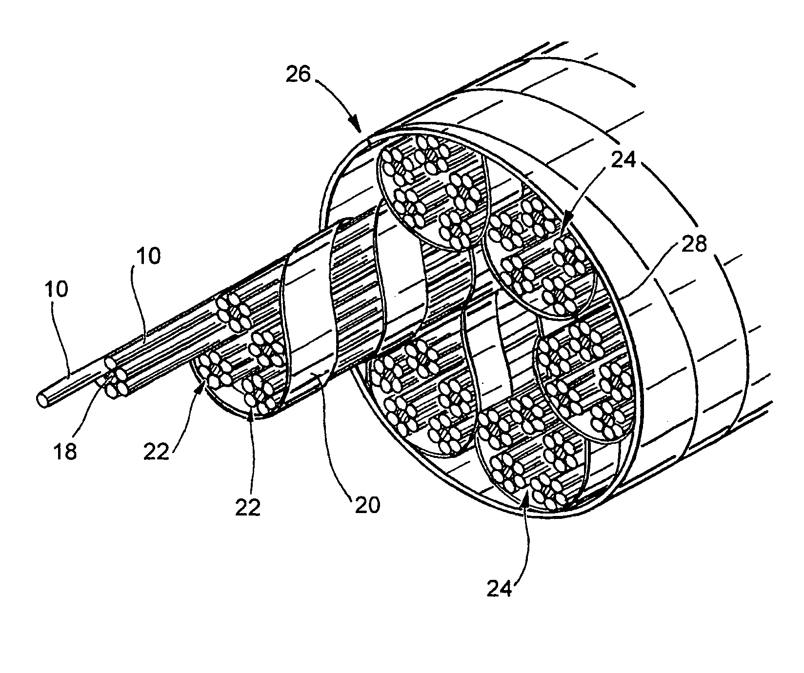
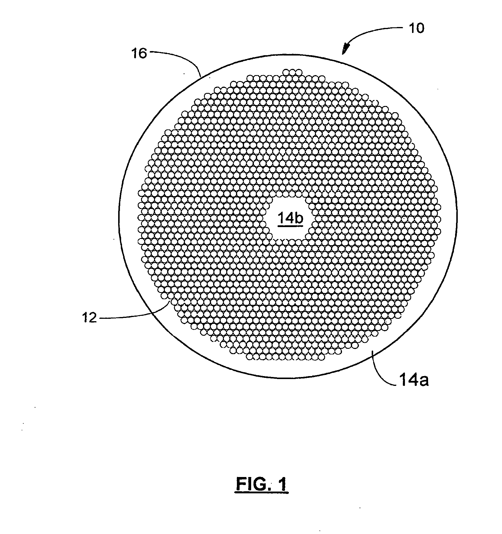
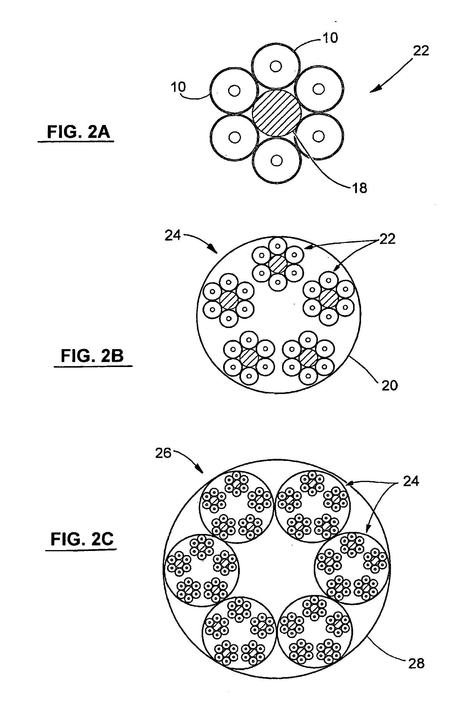
[0020] The electromagnetic behavior of a conductor is dependent on its geometry. Superconducting cables are used for the winding of coils that are intended for the excitation of very strong electromagnetic fields, whereby an electromagnetic field interacts with mechanical vibrations of ionic structure in a conducting medium (e.g., metal) in the presence of a constant magnetic field. On exciting magnetic coils, forces corresponding to the vectorial product of the exciting current and the magnetic induction act on the current conductors. These forces are directional and can cause a deformation of the conductors' cross section and the windings' cross section, as well as a change in the relative position of adjacent conductors. These deformations and changes of position can further cause a decrease in the contact pressure between neighboring conductors and / or a relative displacement of neighboring conductors. Both phenomena are particularly disadvantageous for a superconducting cable.

[...


PUM


Abstract

A cable in conduit superconductor. The superconductor is formed from bundles of superconducting strands made of superconductor filaments, copper, and a layer of electrical resistant material. The superconductor strands are organized around a solid copper central strand, and a plurality of such wires are organized within a circular stainless steel foil, leaving a spiral gap in the middle for liquid coolant to flow. This configuration is then placed within a conduit tubing and compressed for stability.

Description

FIELD AND BACKGROUND OF INVENTION [0001] The present invention relates generally to the field of superconductivity and in particular to a new and improved superconducting cable in a conduit with a special geometry, added materials, and arrangement that reduces hysteresis, eddy current, and AC losses and improves magnet stability. [0002] A superconducting system is disclosed in a prior patent U.S. Pat. No. 6,112,531, the entire disclosure of which is hereby incorporated by reference. The invention disclosed herein enhances the operation of the system disclosed in U.S. Pat. No. 6,112,531. [0003] A conductor's conductivity and resistivity is related to the motion of its free electrons. Electrical current results from the movement of electrons through a material. Electrical resistance arises because electrons propagating through the material are scattered due to deviations caused by impurities in the material or lattice vibrations. Atoms and associated nuclei in a lattice structure can ...

Claims


Application Information

Patent Timeline
IPC IPC(8): H01B12/00H01B12/02H01B12/16
CPCH01B12/02Y02E40/647Y02E40/641H01B12/16Y02E40/60
Inventor BRANDSBERG, TIMOTHY A.BATCHELDER, ROBERT R.WEBER, CHARLES M.KARASIK, VLADIMIR
Owner BWX TECHNOLOGIES
Why Eureka
Try Eureka