[0020] According to the invention, a monolithic ferrule / endcap / optical
fiber structure is provided wherein an optical fiber is terminated in a ferrule and bonded by fusion to form a monolithic unit which minimizes optical loss and is typically capable of transmitting high power laser
radiation, preferably on the order of 500 W and higher, without damage to the optical fiber and ferrule.
[0022]
Polishing and anti-reflection
coating the end-face of this monolithic structure allows radiation to be coupled into and out of the optical fiber core with low loss. As the endcap design
diameter is increased, the
beam size of this radiation on the end-face of the ferrule structure also increases, thereby increasing the optical damage limit of this termination and reducing
coupling of any reflection back into the core of the optical fiber (i.e., “
Return Loss”). If additional reduction of
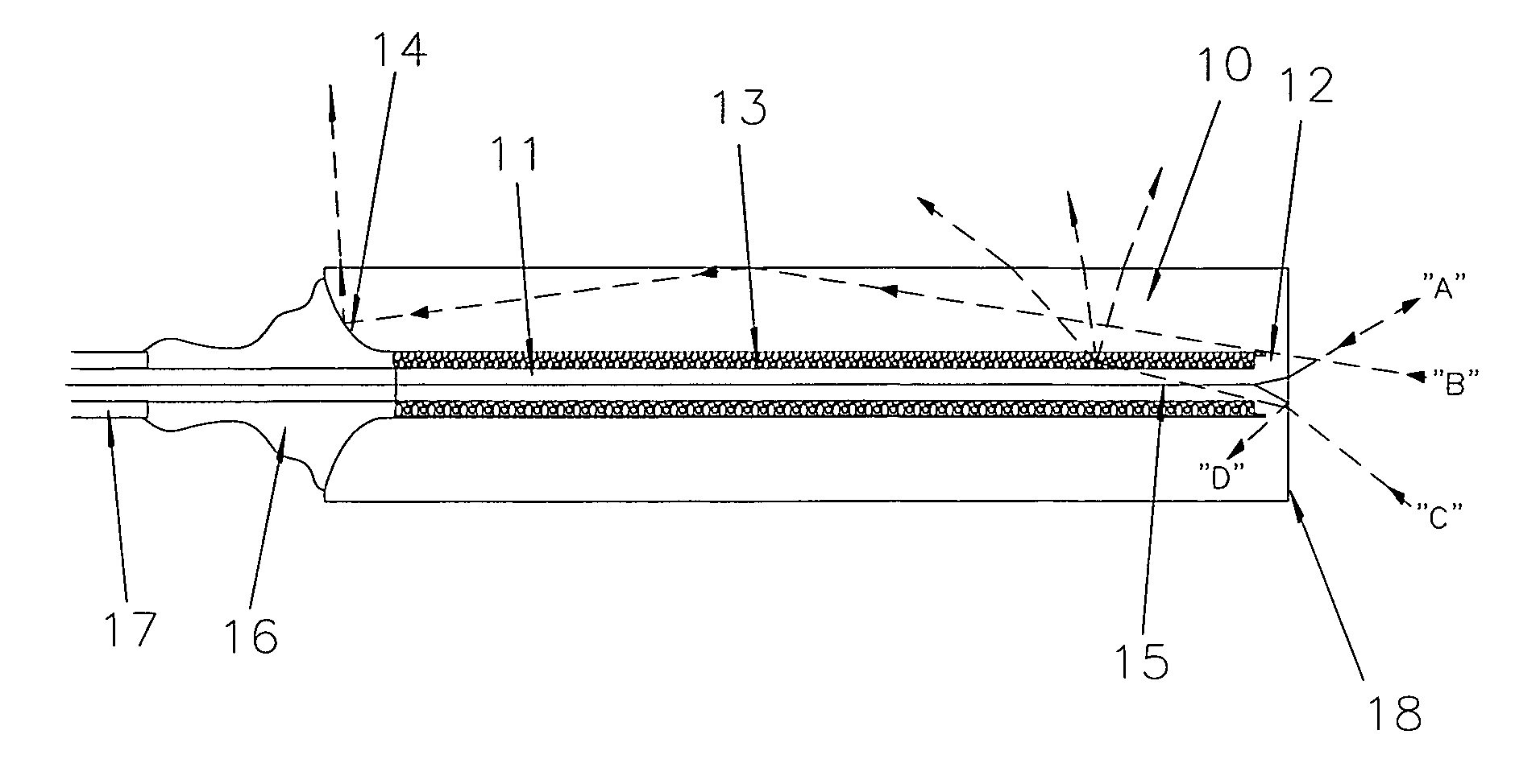
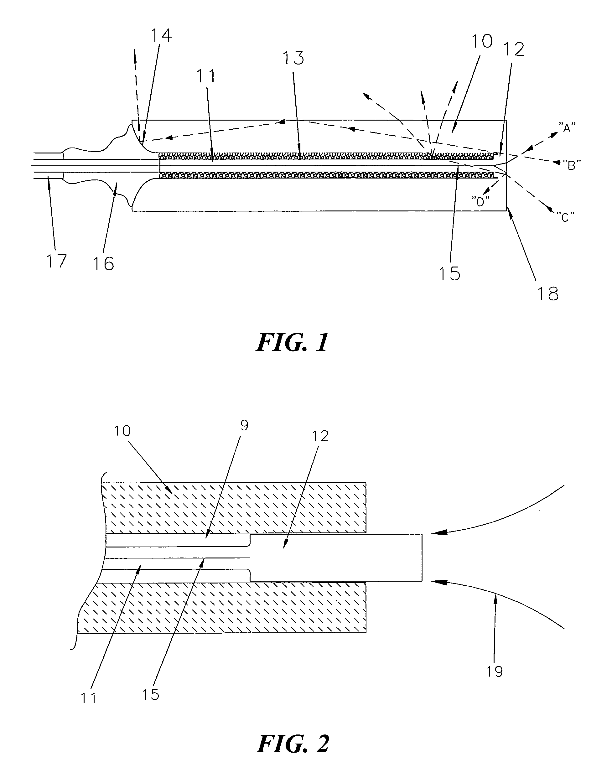
Return Loss is desired the end-face of the monolithic ferrule structure may be angle polished as required. In order to prevent cladding
modes from burning the optical fiber protective
polymer coating during high power operation, the
coating needs to be stripped within the ferrule structure, which leaves a void between the inner
diameter of the ferrule and the outer
diameter of the fiber. According to the invention, this void is filled by placing in the ferrule a
powder that has a higher
refractive index than that of the fiber cladding. The powder is also chosen to have a similar
thermal expansion coefficient, but a lower
softening temperature, than the ferrule material. The powder may be is melted with a localized heat source, such as a laser, to increase optical contact with the optical fiber and ferrule. Bubbles / voids will result in the melted powder regions which cause
diffuse scattering of the mode stripped cladding
modes. The ferrule length is required to be long enough to ensure that all
cladding mode energy ultimately diverges to the cladding of the optical fiber such that it can then be removed by the melted powder mode stripping region.
Radiation scattered in the mode stripping region or entering the ferrule directly that has a
high angle of incidence on the outer diameter surface of the ferrule will be totally reflected at this surface and guided along the ferrule length. In accordance with the invention, this radiation is reflected out of the ferrule structure at the optical fiber end through a flaring at the end of the ferrule and interaction with a reflective coating applied to the surface of the flaring. With substantially all
cladding mode radiation removed, a transmissive
adhesive is provided that strain relieves the optical fiber and a transmissive
polymer adhesive / coating is applied,
recoating any uncoated optical fiber at the flared end of the ferrule structure.
Radiation which is not launched into the fiber core is thereby either scattered or reflected away from the monolithic ferrule structure, where it can be absorbed by heat dissipative and
conductive materials, such as
metal acting as a
heat sink.
[0023] According to another aspect of the invention, a laser is used as a tool to form a lens directly onto the end of the monolithic ferrule structure to achieve a substantially collimated beam out of the ferrule structure thereby forming a monolithic fiber
collimator. To facilitate the formation of the endcap lens of desired size and shape, the ferrule diameter, the length of the protruding endcap prior to fusion / melt back, and the size / shape of the laser radiation focused on the endcap are selected as required. Careful control of the focused laser size, shape and time varied power in relation to the ferrule diameter and endcap protrusion length determines the form of an aspherical lens. Alternatively, or additionally, a sharply focused laser can be scanned across the ferrule end to facilitate the formation of an aspherical lens surface. To form a lens of the desired
focal length, a mirror that is transmissive to the melting laser (e.g. a CO2 laser) is disposed at the desired
collimator waist location.
Radiation suited to the fiber application is launched down the optical fiber. Reflected power of this particular radiation from the mirror at the desired
waist location is monitored with a tap in the optical fiber as the melting laser radiation is applied. When the optimal lens has been formed the melting laser is turned off. In a similar manner, other desired lens powers can be formed for non-collimated beams.
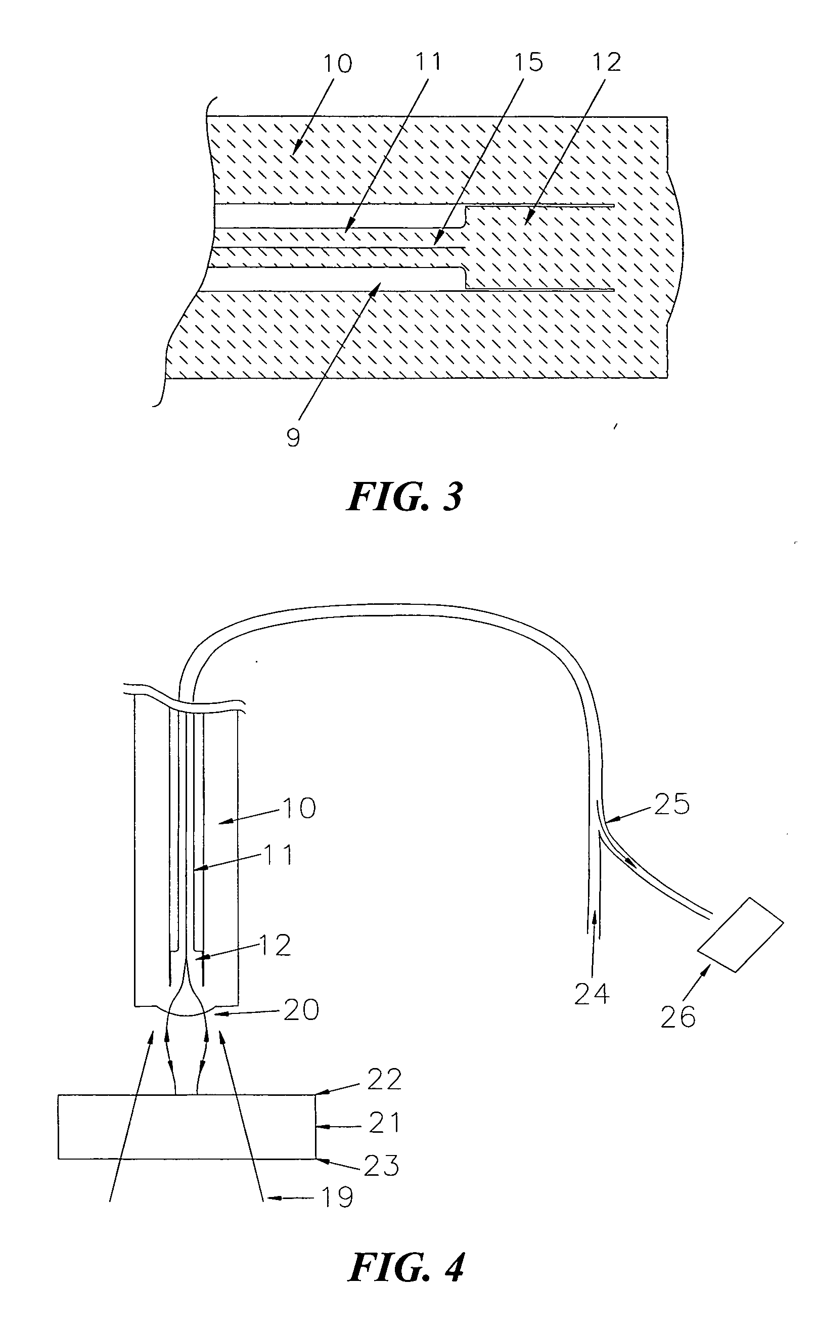
[0026] Another application of the invention is use with
double clad fiber, where the double clad optical fiber is used to confine cladding modes of the inner cladding and prevent them from burning the fiber
polymer protective coating. This configuration requires that any radiation not coupled into the core be confined to the inner cladding region only. Because the outer cladding confines inner cladding modes, the
double clad fiber can be made as long as desired, allowing for an inner
cladding mode stripping ferrule according to the invention to be located remote from the fiber termination. This can be particularly useful for very high power if water-cooling of the mode-stripping ferrule is impractical or undesirable at the fiber termination. The endcap and
double clad fiber can be the same diameter, and the termination ferrule /
collimator structure can be relatively short, since the mode stripping occurs in the remote mode stripping ferrule. “Jacketed air clad fiber” and
photonic crystal fiber can also be used in place of conventional double clad fiber. In such cases, the
single core fiber may be large mode area fiber—with a
mode field diameter consistent with these fiber types.

